Film-clad battery and method of producing film-clad battery

a film-covered battery and film-clad technology, applied in the field of film-clad battery and method of producing film-clad battery, can solve the problems of cracking, damage to the performance and reliability of film-covered battery, etc., and achieve the effect of facilitating folding operation, improving the performance and reliability of the battery, and preventing damage to the covering material

Active Publication Date: 2007-01-11
NEC CORP
View PDF5 Cites 6 Cited by
  • Summary
  • Abstract
  • Description
  • Claims
  • Application Information

AI Technical Summary

Benefits of technology

[0024] As described above, since the present invention forms a folded portion of the joint section of the covering films so that it is thinner, the folding operation is facilitated. Also, since the elongation on the outer side is reduced when the joint section is folded, the covering material can be prevented from incurring damage. From the foregoing, the present invention can prevent a crack from opening in the middle of the joint section to form a short transmission path into the interior of the battery, and can also prevent the introduction of moisture and the escape of an electrolytic solution from accelerating, thus making it possible to improve the performance and reliability of the battery.

Problems solved by technology

However, the foregoing folded joint section of the conventional film-covered battery causes a problem of possible damage such as cracks that open in the folded portion because of the inability of the outside layer to follow elongation of the film.
However, as illustrated in FIG. 3, when this joint section is folded from the bottom substantially at right angles toward the battery element receiving section, a layer on outer side 106a of the fold is elongated to become thinner, possibly causing a crack to appear.
If a crack opens in thin metal film 102d layer, a leak path is created through the crack, and a short transmission path is formed from the crack to the interior of the battery, resulting in possible damage to the performance and to the reliability of film-covered battery 101.

Method used


Image

  • Film-clad battery and method of producing film-clad battery
  • Film-clad battery and method of producing film-clad battery
  • Film-clad battery and method of producing film-clad battery

Examples


first embodiment

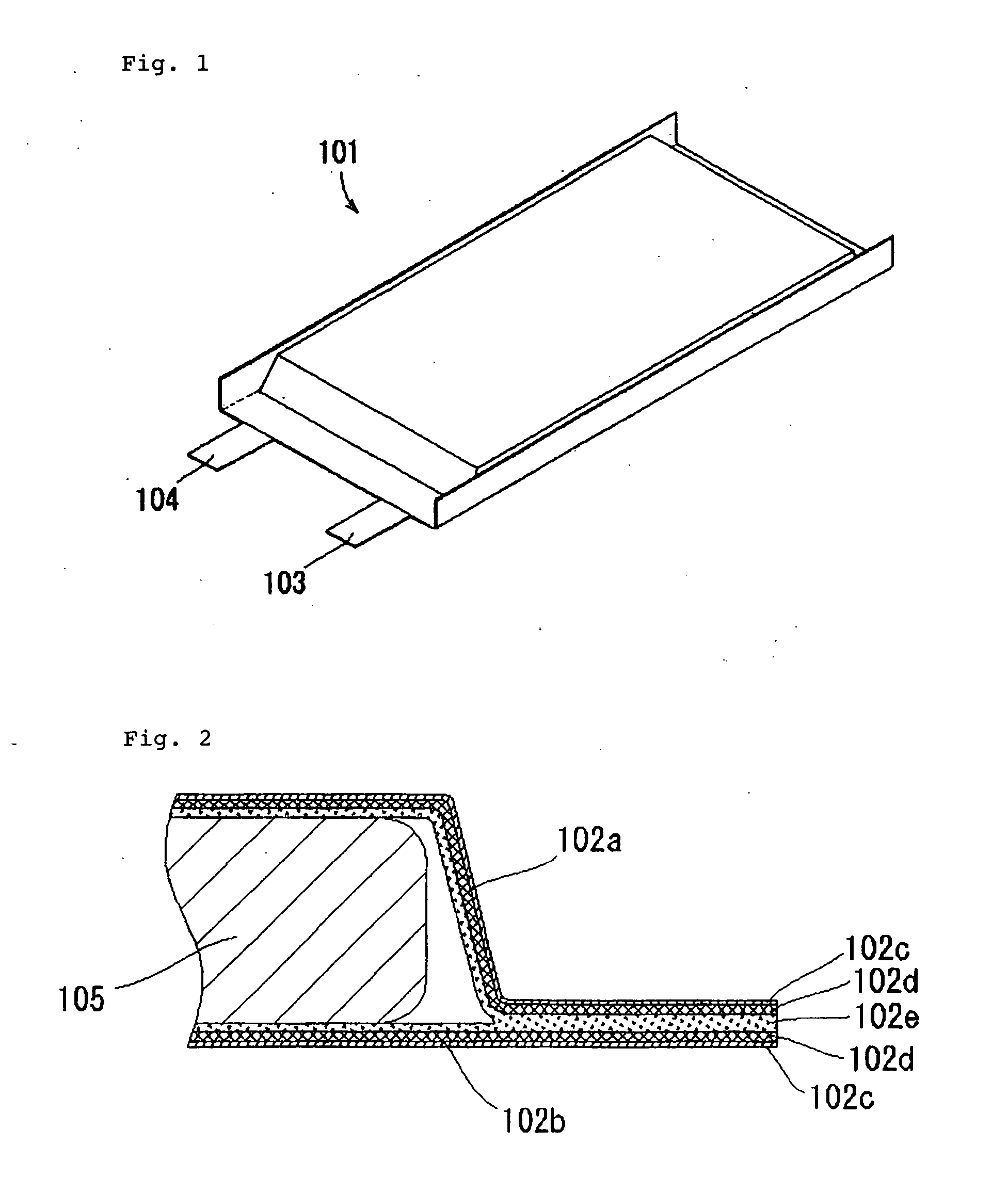
[0046]FIG. 4 is a perspective view illustrating the appearance of a film-covered battery according to a first embodiment of the present invention, FIG. 5 is an exploded perspective view illustrating the configuration of the film-covered battery illustrated in FIG. 4, and FIG. 6 is a perspective view illustrating the state of the film-covered battery illustrated in FIG. 4 before a joint section is folded. In this regard, FIG. 5 illustrates a film-covered battery which is not formed with a groove that is a feature of the present invention.

[0047] As illustrated in FIG. 5, film-covered battery 1 of this embodiment comprises laminate type battery element 5 (see FIG. 20) having positive electrode plates 8 and negative electrode plates 9 laminated through separators 10; rectangular covering films 2a, 2b for receiving battery element 5 together with an electrolytic solution; and positive electrode's lead terminal 3 and negative electrode's lead terminal 4 connected to a positive electrode ...

second embodiment

[0055] Next, a film-covered battery according to a second embodiment of the present invention will be described with reference to FIGS. 10 to 15. In this regard, since the film-covered battery of this embodiment is similar in basic structure, groove forming method, and structure to the film-covered battery of the first embodiment, a detailed description is omitted.

[0056] While the first embodiment has shown a configuration in which the battery element is encapsulated by two covering films, and sealed by heat-sealing the four sides therearound, film-covered batteries 11, 21 of this embodiment have battery elements 15, 25 encapsulated in folded single covering films 12, 22, and sealed by heat-sealing the three surrounding sides.

[0057] In an example of FIGS. 10-12, groove 16 is formed along one side opposing a side created by folding covering film 12, and a joint section thereof is folded toward receiving section 12a1 which receives battery element 15. FIG. 10 is a perspective view i...

third embodiment

[0064] Next, a film-covered battery according to a third embodiment of the present invention will be described with reference to FIGS. 16-19. In this regard, since the film-covered battery of this embodiment is similar in basic structure, groove forming method, and structure to the film-covered battery of the first embodiment, a detailed description is omitted.

[0065] The film-covered battery according to the third embodiment of the present invention has a heat-sealed section of covering films folded a plurality of times to further reduce the projection area of the film-covered battery. FIGS. 16 and 17 illustrate an example in which two grooves are formed along one side, while FIGS. 18 and 19 illustrate an example in which three grooves are formed along one side.

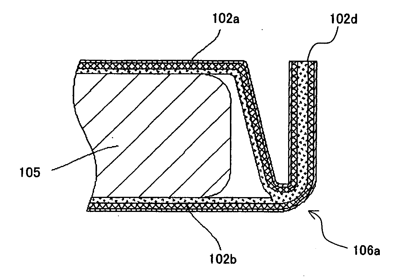
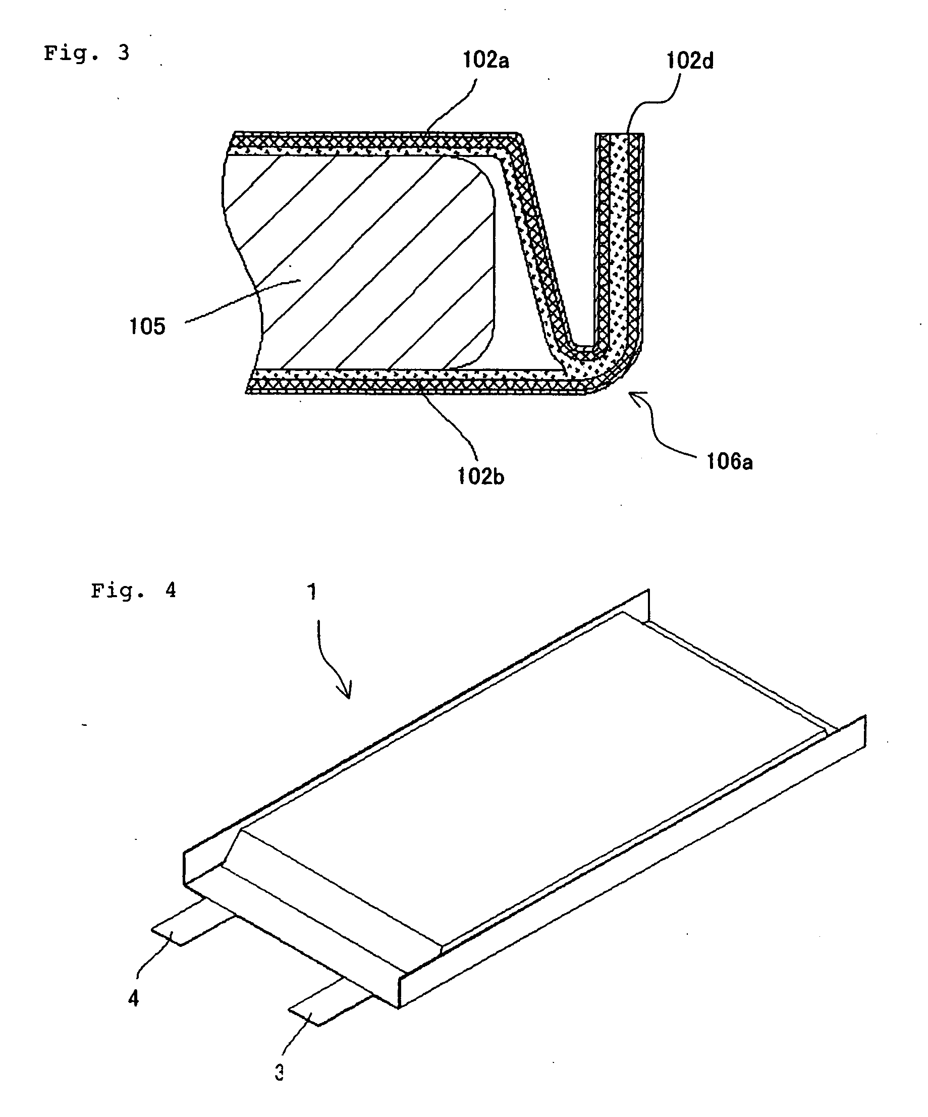
[0066]FIG. 16 is a perspective view illustrating the appearance of the film-covered battery having two grooves formed along one side according to the third embodiment of the present invention, and FIG. 17 is a perspective v...


PUM

PropertyMeasurementUnit
angleaaaaaaaaaa
thicknessaaaaaaaaaa
thicknessaaaaaaaaaa

Abstract

A joint section where covering films 2a, 2b of film-covered battery 1 are heat-sealed together is formed with flat surface 6′ having thickness t1 and groove 6 having thickness t2. Groove 6 serves to reduce the projection area of film-covered battery 1 by folding side 2c toward receiving section 2a1 with groove 6 serving as an edge, and groove 6 is made thinner than flat surface 6′ by Δ t=t1−t2. Therefore, the length of covering films 2a, 2b produced on outer side 6a is shortened as compared with the case of folding the portion that has thickness t1.

Description

TECHNICAL FIELD [0001] The present invention relates to a film-covered battery which has a battery element encapsulated in a flexible materials used to cover the battery, and a method of producing the film-covered battery. BACKGROUND ART [0002] In recent years, a reduction in weight and thickness has been strictly required for batteries as a power supply for portable devices and the like. Thus, in regard to materials used to cover the batteries, laminate films capable of a further reduction in weight and thickness have been used more and more instead of conventional metal cans in which there is a limit to weight and thickness reductions. This laminate film which can be freely formed into different shapes, compared with a metal can, comprises a thin metal film or a laminate of a thin metal film and a heat-seal resin film. [0003] As a representative example of a laminate film used for materials used to cover the batteries, there is a three-layer laminate film that has a heat-seal resi...

Claims


Application Information

Patent Timeline
Patent Type & Authority Applications(United States)
IPC IPC(8): H01M2/08H01M10/04H01M2/02B29C53/06B29C59/00B29C65/00B29C65/02H01G9/08H01G11/00H01G11/12H01G11/66H01G11/74H01G11/78H01G11/80H01G11/84H01M50/124H01M50/178H01M50/184H01M50/55H01M50/557
CPCB29C53/063Y10T29/4911B29C65/02B29C66/0324B29C66/433B29C66/4332B29C66/80B29L2009/00B29L2031/7146H01G9/08H01G13/003H01M2/0212H01M2/0267H01M2/0275H01M2/0287B29C59/007Y10T29/49108H01M2/08H01M2/021B29C65/00B29C66/83221B29C65/08B29C66/72321B29C66/7234B29C66/1122Y02E60/10B29L2031/3468B29C66/53461B29C66/131B29C66/112H01M50/557H01M50/124Y02P70/50H01M50/178H01M50/184H01M50/55B29C66/81427B29C66/306B29L2031/7128B29C53/06H01M50/119H01M50/121
Inventor OTOHATA, MAKIHIROYAGETA, HIROSHI
Owner NEC CORP
Why Eureka
Try Eureka