Tool with a carrier part and a disc-shaped working part

Inactive Publication Date: 2007-01-11
FA AUGUST RUGGEBRERG
View PDF4 Cites 3 Cited by
  • Summary
  • Abstract
  • Description
  • Claims
  • Application Information

AI Technical Summary

Benefits of technology

[0006] It is an object of the invention to design a generic tool such that the making and breaking of the connection between the carrier part and the working part can be executed in a quick and simple way.

Problems solved by technology

Normally, the attaching and detaching of the working part from the carrier part is cumbersome or time-consuming or can only be accomplished the utmost care.
This is disturbing because working parts of this kind very often have to be replaced after only a short time of use.
Particularly in such a case the stack height of the working parts is also very great because the coupling part with the female thread inevitably exhibits a considerable height.
This is unsuitable for the tools of the aforementioned kind.

Method used


Image

  • Tool with a carrier part and a disc-shaped working part
  • Tool with a carrier part and a disc-shaped working part
  • Tool with a carrier part and a disc-shaped working part

Examples


Embodiment Construction

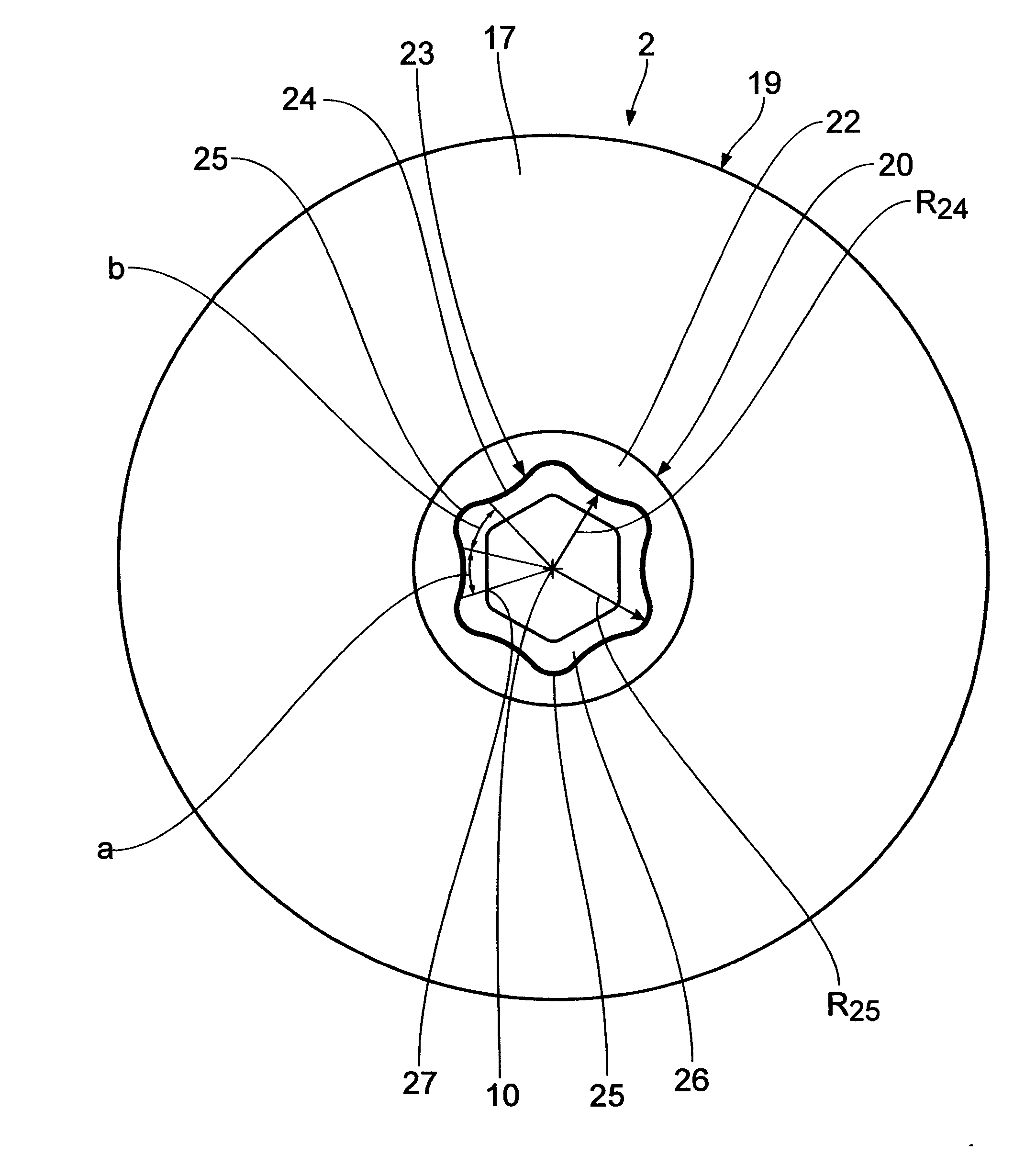
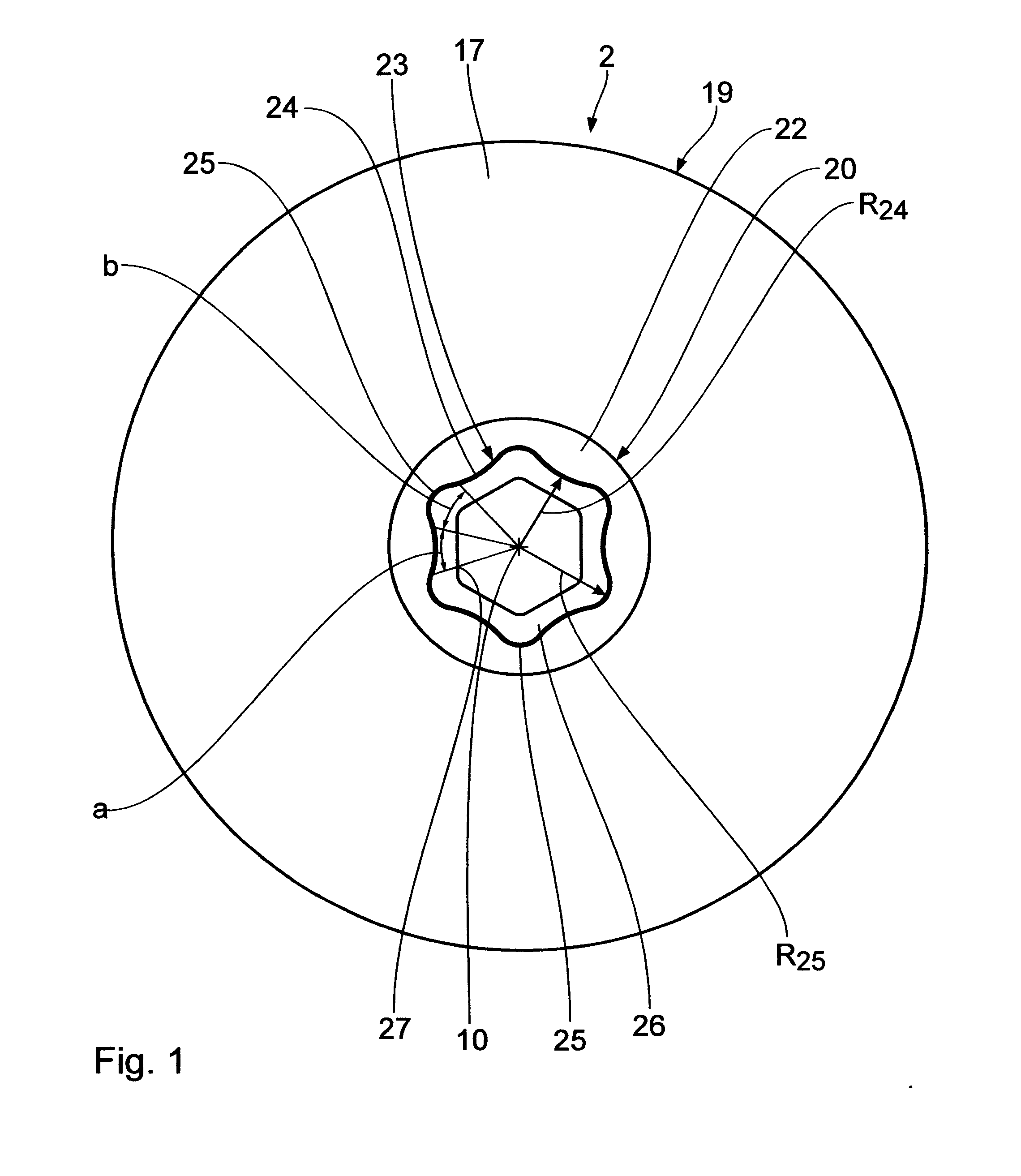
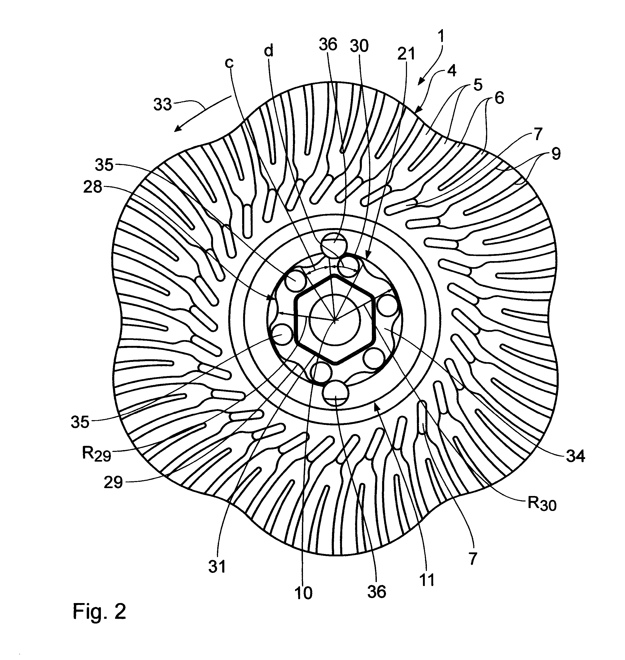
[0012] In its basic configuration the tool shown in the drawing consists of a carrier part 1 in the form of a bracing plate and a working part 2. The carrier part 1 exhibits a holding body 3, onto which there is sprayed a carrier plate 4 made of rubber. Said carrier plate 4 is equipped with cooling channels 5 running from the inside to the outside, which are separated from each other by means of ribs 6 also running from the inside to the outside. At their inside end, the cooling channels 5 are each connected to the atmosphere via an air inlet aperture 7 on the back side 8 of the carrier plate 4. The top sides of the ribs 6 opposite to the back side 8 limit an abutting surface 9 for the working part 2. This design of the carrier plate 4 with cooling channels 5 is shown and described in DE 10 2004 009 443 A, to which reference is made.

[0013] In the holding body 3, in turn, there is arranged concentrically in relation to a common central longitudinal axis 10 an accommodating body 11, ...


PUM


Abstract

A tool exhibits a carrier part and a disc-shaped working part for chip-forming machining. The two parts are detachably connected with each other by means of a coupling part and a counter-coupling part that inter-lock. They exhibit convex and concave wall sections adapted to each other. Moreover, there is created a latch-in connection by an inside hexagon aperture and an outside hexagon.

Description

BACKGROUND OF THE INVENTION [0001] 1. Field of the Invention [0002] The invention relates to a tool with a carrier part and a disc-shaped working part for chip-forming machining. [0003] 2. Background Art [0004] Tools of the generic type, where a carrier part or a base body are each connected to a working part that is a wear part, are known in diverse embodiments. Working parts of this kind are, for example, abrasive means on a base, polishing discs and cleaning discs or felt discs consisting of needle fleece with an imbedded abrasive means. The carrier part and the working part are rotationally driven. On known embodiments there is fitted on the side opposite to the working side, a coupling part with a female thread, which is screwed onto the thread of a carrier part. Normally, the attaching and detaching of the working part from the carrier part is cumbersome or time-consuming or can only be accomplished the utmost care. This is disturbing because working parts of this kind very of...

Claims


Application Information

Patent Timeline
IPC IPC(8): B23F21/03
CPCB24B45/003B24D13/20B24D9/085
Inventor STEIN, MARKUSHUTH, NICOLAS
Owner FA AUGUST RUGGEBRERG
Why Eureka
Try Eureka