Methods and apparatus for optimizing well production

a well and production method technology, applied in the direction of well accessories, borehole/well, fluid removal, etc., can solve the problems of reducing the production output of the well, cyclical well production, and insufficient production of the well, so as to achieve the effect of optimizing the well's production

Active Publication Date: 2007-01-18
WEATHERFORD TECH HLDG LLC
View PDF31 Cites 33 Cited by
  • Summary
  • Abstract
  • Description
  • Claims
  • Application Information

AI Technical Summary

Benefits of technology

[0018] In another embodiment, a method of optimizing an artificial lift cycle of a well comprises measuring a first production of the well in a first cycle of operation; measuring a second production of the well in a second cycle of operation; comparing the first production to the second production; and adjusting one or more well operating parameters in response to the comparison. In another embodiment, the method further comprises relating each of the first production and the second production to a daily production of the well.
[0019] In another embodiment, an automated method and apparatus for operating an artificial lift well is provided. An on-cycle of the well is initiated based on a pressure differential measured between a casing pressure and a sales line pressure. When a predetermined ON pressure differential is observed, a controller initiates the on-cycle and opens a motor valve to permit fluid and gas accumulated in the tubing to flow out of the well. Thereafter, a mandatory flow period is

Problems solved by technology

In a gas well, the accumulated fluids block the flow of the formation gas into the borehole and reduce the production output from the well.
The use of artificial lift systems results in the cyclical production of the well.
During the off-cycle, the well is “shut-in” and not productive.
Deriving the time interval of these cycles has always been difficult because production parameters considered for this task are different in every well and the parameters associated with a single well change over time.
For instance, as the production parameters change, a plunger lift system operating on a short timed cycle may lead to an excessive quantity of liquids within

Method used


Image

  • Methods and apparatus for optimizing well production
  • Methods and apparatus for optimizing well production
  • Methods and apparatus for optimizing well production

Examples


Embodiment Construction

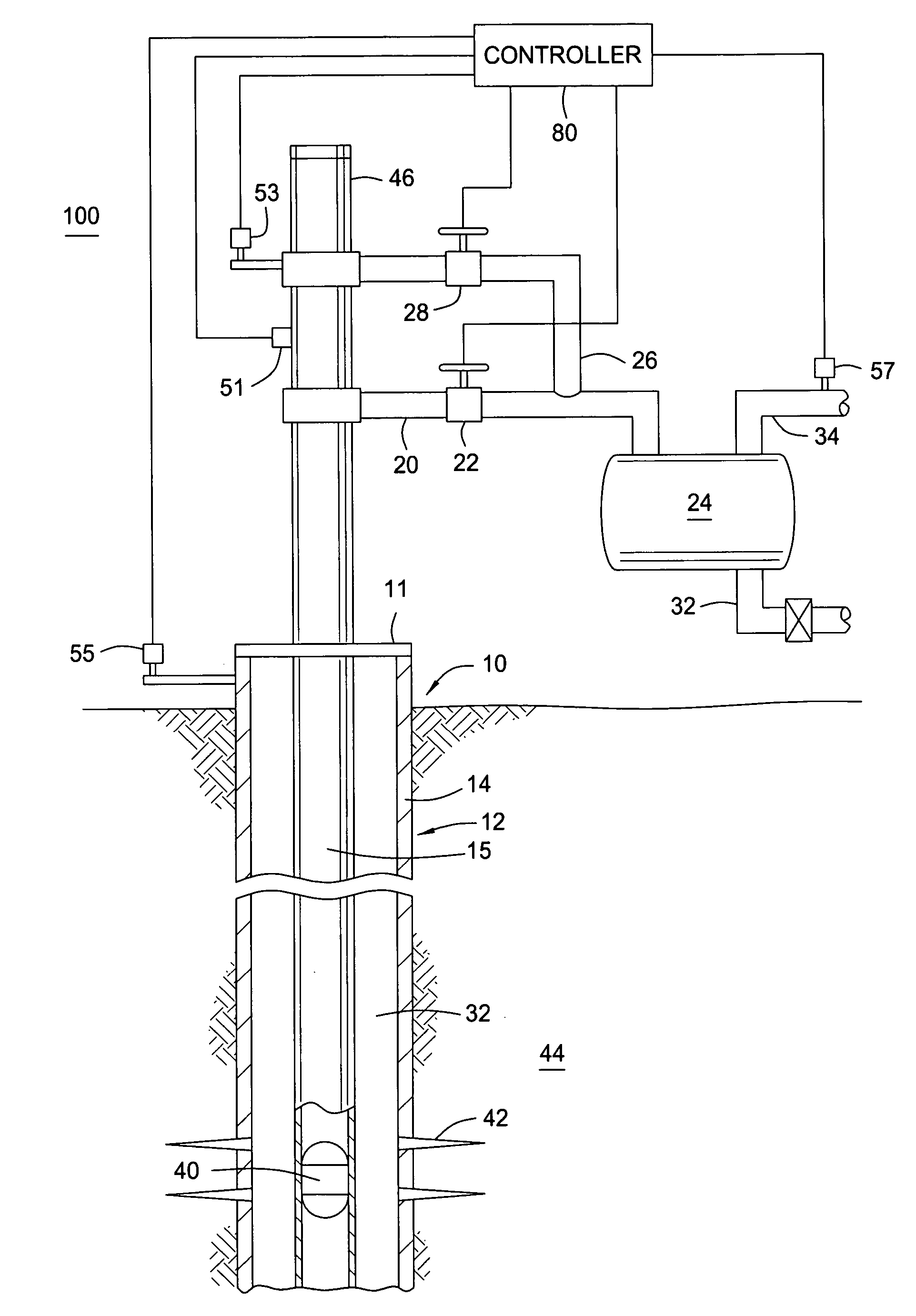
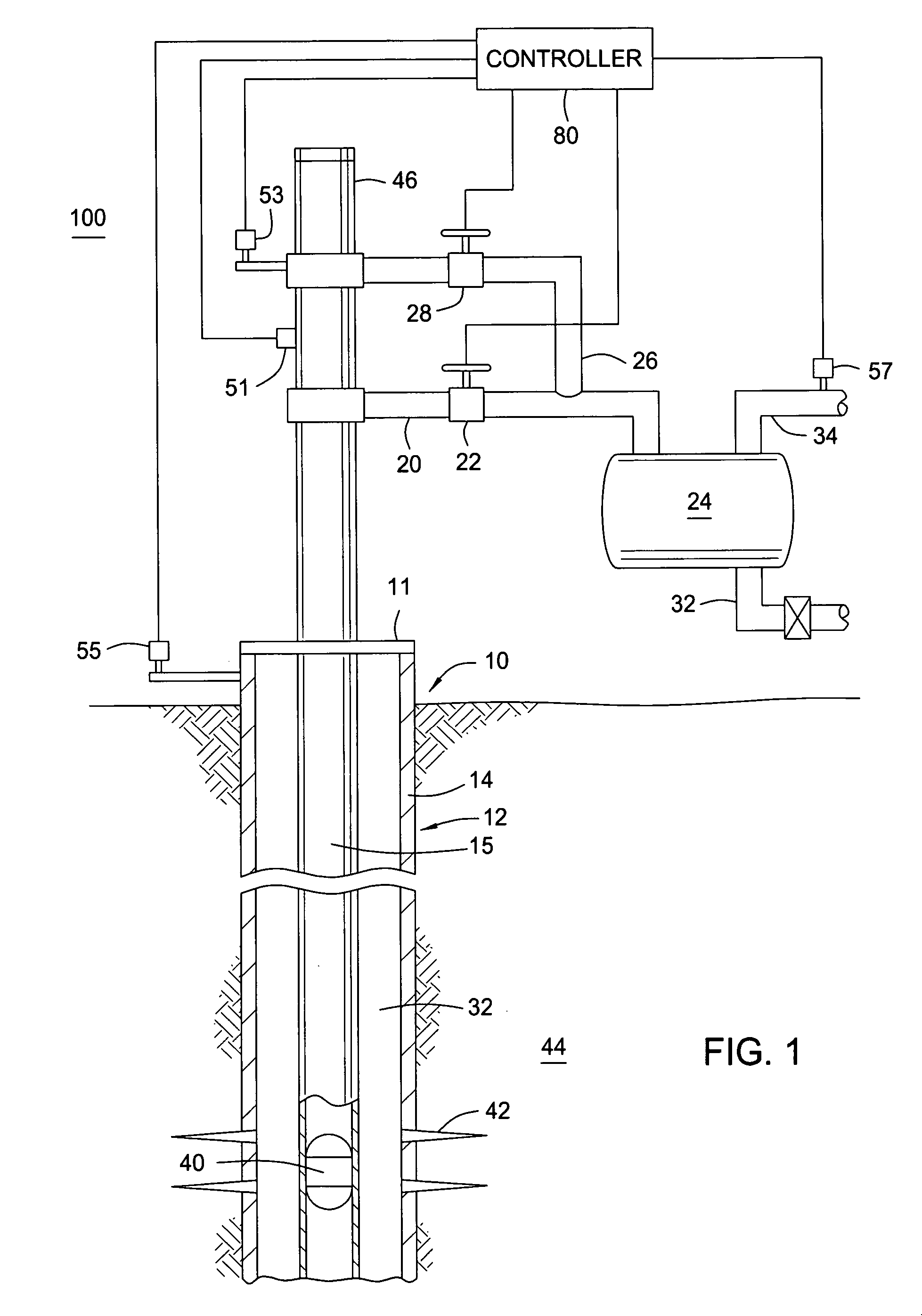
[0026]FIG. 1 is a schematic view of an embodiment of the present invention applied to a plunger lift system 100. The well 10 includes a wellbore 12 which is lined with casing 14 and a string of production tubing 15 disposed therein. Perforations 42 are formed in the casing 14 for fluid communication with an adjacent formation 44. The production tubing 15 and casing 14 extend from a well head 11 located at the surface to the bottom of the well 10. A plunger 40 is disposed at the bottom of the tubing 15 when the system 100 is shut-in. A lubricator 46 for receiving the plunger 40 is disposed at the top of the tubing 15. The lubricator 46 includes a plunger arrival sensor 51 for detecting the presence of a plunger 40 and a tubing pressure sensor 53 to monitor the pressure in the tubing 15. The casing pressure, which is the pressure in an annular area 32 defined by the exterior of the tubing 15 and the interior of the casing 14, is monitored by a casing pressure sensor 55 disposed adjace...


PUM


Abstract

Embodiments of the present invention generally relates to methods and apparatus for operating an artificial lift well. In one embodiment, the well is operated between an on cycle and an off cycle. Preferably, the off cycle is determined by detecting an increase in the pressure differential between the casing pressure and the tubing pressure. In another embodiment, the well is optimized by measuring the production of the well in one cycle of operation. The measured production is compared to the production of a previous cycle. A controller then optimizes the well based on the increase or decrease of the production from the previous cycle.

Description

BACKGROUND OF THE INVENTION [0001] 1. Field of the Invention [0002] Embodiments of the present invention generally relate to optimizing production of hydrocarbon wells. Particularly, embodiments of the present invention relate an artificial lift system for moving wellbore fluids. More particularly, embodiments of the present invention relate to optimizing the production of a hydrocarbon well intermitted by a plunger lift system. [0003] 2. Description of the Related Art [0004] The production of fluid hydrocarbons from wells involves technologies that vary depending upon the characteristics of the well. While some wells are capable of producing under naturally induced reservoir pressures, more common are wells that employ some form of an artificial lift production technique. During the life of any producing well, the natural reservoir pressure decreases as gas and liquids are removed from the formation. As the natural downhole pressure of a well decreases, the wellbore tends to fill u...

Claims


Application Information

Patent Timeline
IPC IPC(8): E21B43/12
CPCE21B47/06E21B43/121E21B43/12E21B43/122
Inventor HEARN, WILLIAM
Owner WEATHERFORD TECH HLDG LLC
Why Eureka
Try Eureka