
Combination thermostat and warning device with remote sensor monitoring

a technology of thermostat and remote sensor, applied in the field of electronic warning devices, can solve the problems of sirens, church bells, other means of providing, and the inability to provide immediate and complete coverage to all residential, commercial and public facilities, and achieve the effect of improving coverag

Inactive Publication Date: 2007-01-18
RANCO OF DELAWARE
View PDF20 Cites 61 Cited by
  • Summary
  • Abstract
  • Description
  • Claims
  • Application Information

AI Technical Summary

Benefits of technology

"The present invention is a combination thermostat and severe weather warning device that can be permanently installed in a home or other structure. The device incorporates a housing that looks like a regular thermostat but includes a NOAA weather radio for receiving severe weather broadcasts and alarms. The device uses electrical energy from the home's standard electrical supply and also includes a backup battery power in case of power interruption. The device can also function as an alarm point for other devices like smoke detectors, doorbells, and security alarms. The device can also include control elements that allow it to function as a weather station and manage the energy consumption of the home's environmental conditioning system. The device can also use the NOAA radio to receive price signals and act as a central reception point for utility pricing data. Overall, the device provides a comprehensive solution for protecting homes and buildings from severe weather and other emergency situations."

Problems solved by technology

Community wide systems of sirens, church bells and other means of providing large geographic area alerts, while effective at times, fall short of the providing immediate and complete coverage to all residential, commercial and public facilities.

Method used


Image

  • Combination thermostat and warning device with remote sensor monitoring
  • Combination thermostat and warning device with remote sensor monitoring

Examples


Embodiment Construction

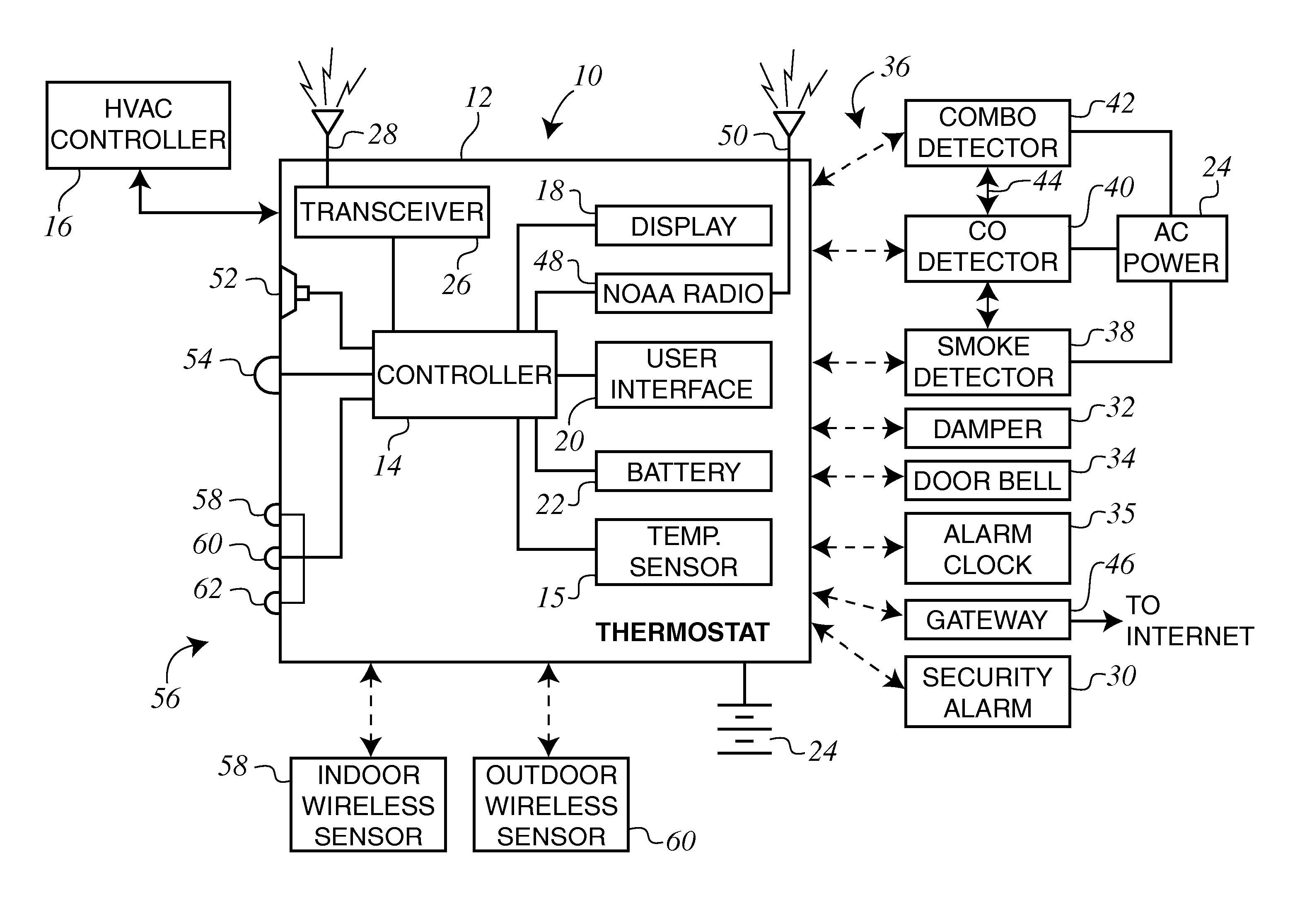
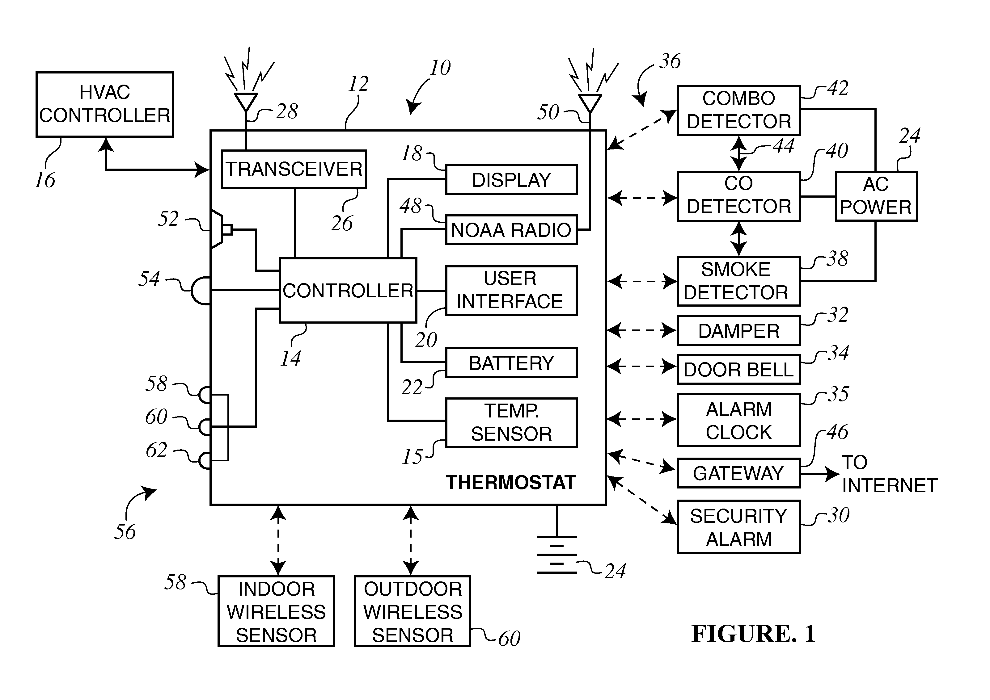
[0021] The present invention comprises a combination thermostat and warning device 10, with all internal components being contained within a common housing 12. The drawing FIGURE provides a block diagram of the basic and optional componentry of the present invention, including the common housing 12. It should be understood that the housing 12 may have any appearance or configuration as desired, so long as appropriate conventional apertures, openings, and / or passages are provided for access to such internal components as function controls, battery access for replacement, connections for external or remote components, etc. as desired.

[0022] As illustrated in the FIGURE, the combination thermostat 10 includes a central controller 14 that controls the operation of the normal thermostat functions, such as monitoring the temperature and or humidity in the area immediately surrounding the thermostat as sensed by the temperature / humidity sensor 15 and controlling the operation of a climate...


PUM


Abstract

A combination thermostat and warning device that is housed within a common housing, such as a housing resembling that for a conventional thermostat. The combination device includes a controller that is operable to control the operation of a climate control device, such as an HVAC system. The combination thermostat and warning device includes a radio receiver that is disposed within the common housing and receives warning radio broadcasts from a remote source, such as the National Oceanic and Atmospheric Administration (NOAA). The controller of the combination thermostat and warning device controls the generation of a warning alarm by an alarm indicator based upon the warning radio broadcast to alert occupants of the warning broadcast. The warning alarm can be generated by an alarm indicator included within the common housing or can be generated by remote devices, such as hazardous condition detectors or other alarm system. The combination thermostat and warning device includes a transceiver that can both broadcast messages to remote devices and receive information from remote devices, such as remote temperature sensors.

Description

CROSS REFERENCE TO RELATED APPLICATION [0001] The present application is based on and claims priority to U.S. Provisional Patent Application Ser. No. 60 / 698,782, filed on Jul. 13, 2005.FIELD OF THE INVENTION [0002] The present invention relates generally to electronic warning devices, and more specifically to a combination thermostat and severe weather warning device. The combination device houses a conventional thermostat control circuit and an FM radio that receives area-specific severe weather alerts and broadcasts from the National Oceanic and Atmospheric Administration (NOAA), according to the area of concern. The thermostat is part of an integrated home system and communicates using wireless communication techniques (RF) with other home devices, such as smoke and CO detectors, to generate alarm signals. BACKGROUND OF THE INVENTION [0003] Most, if not all, areas of the country have building codes requiring that smoke detectors or smoke alarms be installed in almost all structur...

Claims


Application Information

Patent Timeline
Patent Type & Authority Applications(United States)
IPC IPC(8): G08B17/00
CPCG08B27/008G08B7/06
Inventor EHLERS, GREGORY A.
Owner RANCO OF DELAWARE
Learn More