Cao fuel cell stack with large specific reactive surface area

a fuel cell and reactive surface technology, applied in the field of fuel cell stack construction, can solve the problems of low power density per unit volume, large total power requirement, and serious limitations of direct liquid-feed fuel cells, and achieve the effect of substantially increasing the reactive surface area per unit volume and efficiently producing

Inactive Publication Date: 2007-01-18
CAO YIDING
View PDF5 Cites 15 Cited by
  • Summary
  • Abstract
  • Description
  • Claims
  • Application Information

AI Technical Summary

Benefits of technology

[0006] Another objective of the present invention is to provide means for distributing the fuel to the anodes of the fuel cell units and for distributing the oxidant to the cathodes of the fuel cell units with maximum contact surface areas between the fuel flow streams and the anodes and between the oxidant fl

Problems solved by technology

In this case, the total power requirement is substantial and the size limitation is very stringent due to the small size of the vehicle.
One of the most serious limitations related to a direct liquid-feed fuel cell is its very low power density per unit reactive surface area.
This indicates that a higher cu

Method used


Image

  • Cao fuel cell stack with large specific reactive surface area
  • Cao fuel cell stack with large specific reactive surface area
  • Cao fuel cell stack with large specific reactive surface area

Examples


Embodiment Construction

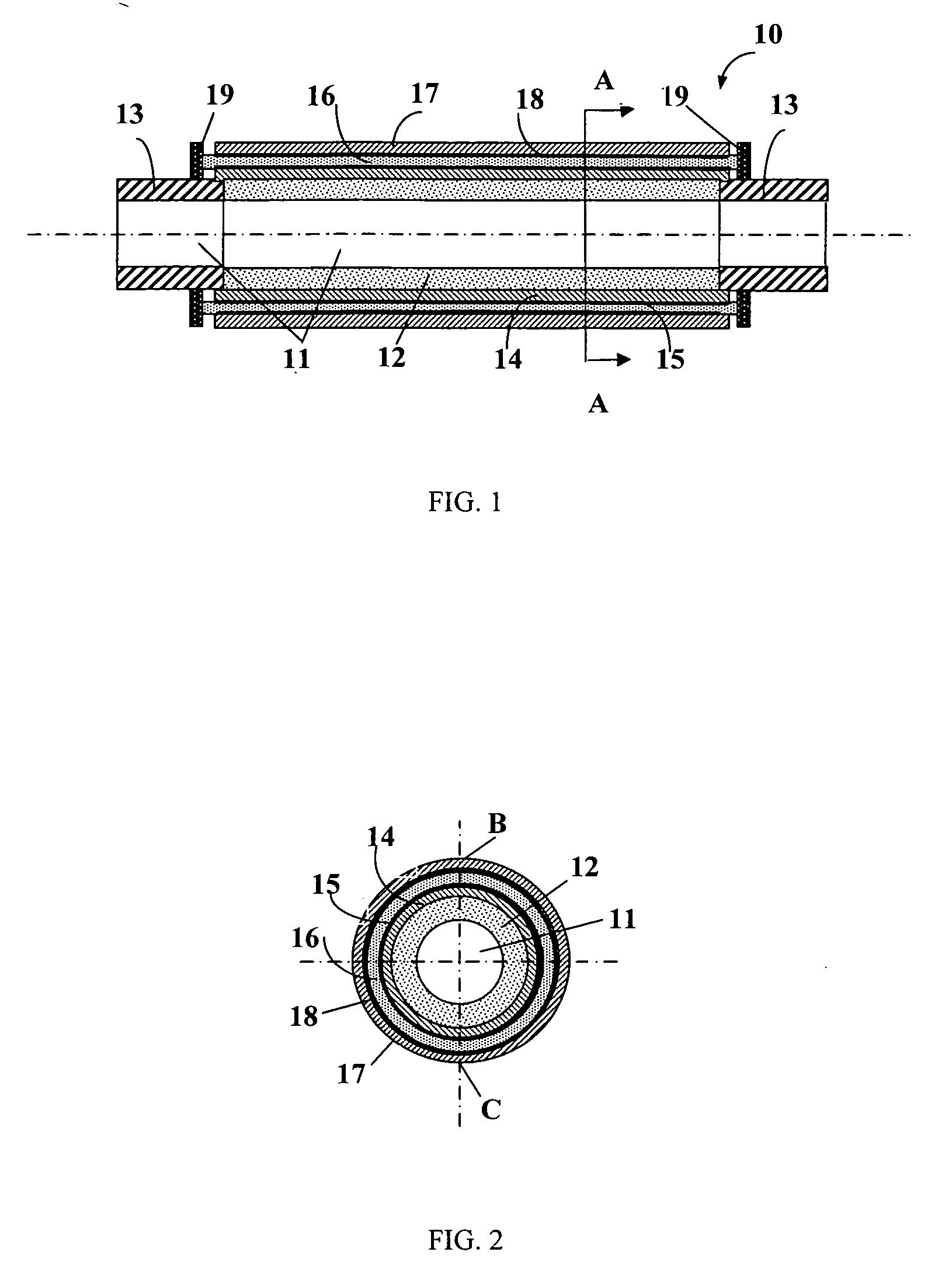
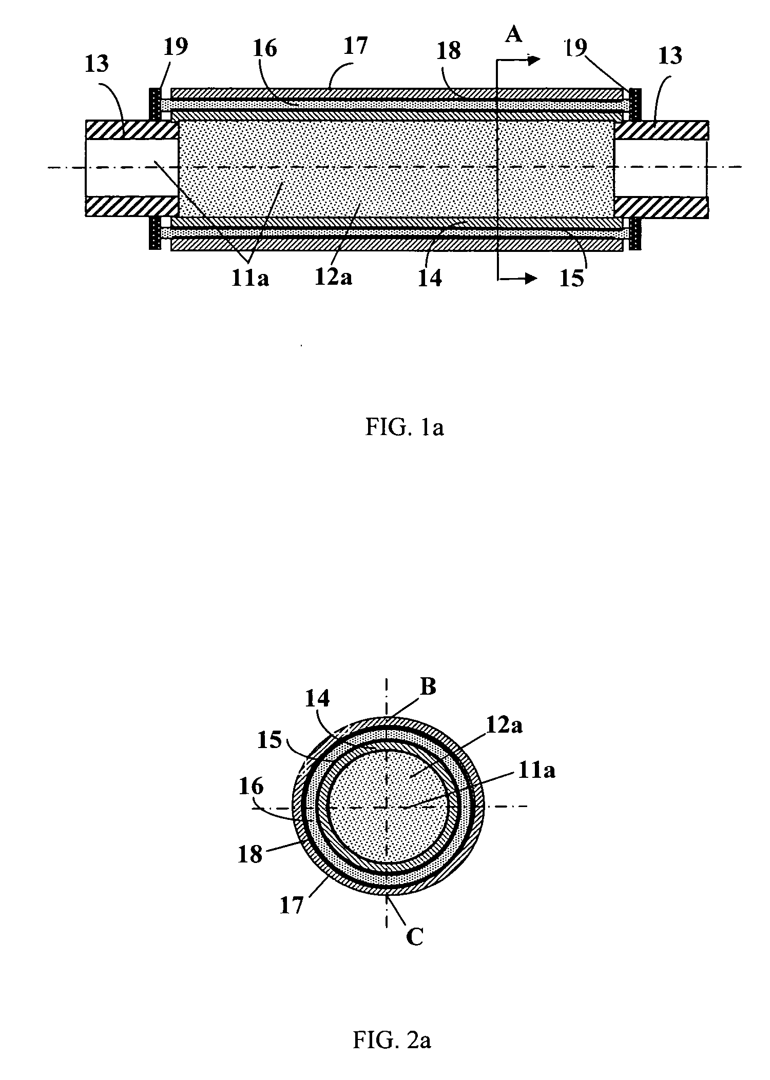
[0022]FIG. 1 shows schematically a micro cylindrical fuel cell unit 10 constructed based on a micro porous tube, and FIG. 2 is a cross-sectional illustration of the fuel cell unit shown in FIG. 1. The micro fuel cell unit has a generally circular cross section. In the context of this disclosure, the term “generally circular cross section” means that the cross section may be circular, elliptical, pentagonal, or hexagonal, etc., although a circular shape is preferred. The term “micro” used in this disclosure means the fuel cell unit's diameter or the “hydraulic diameter” as defined in Fluid Mechanics is on the order of 1 mm. Depending on a specific design, the actual diameter of a cylindrical fuel cell unit can be greater than 1 mm or less than 1 mm in the range of micrometers. With reference to FIG. 1, the fuel cell unit 10 has a generally circular micro tube 11, which defines an axial flow path for a fuel stream or an oxidant flow stream and comprises a porous (permeable) wall secti...


PUM


Abstract

A fuel cell stack is constructed based on a plurality of micro fuel cell units having a generally circular cross section. Each micro fuel cell unit includes an electric conductive tube that comprises a porous wall section and a non-permeable wall section, an inner electrode being disposed coaxially around and in intimidate contact with the peripheral surface of the porous wall section, a solid electrolyte member being disposed coaxially around and in intimate contact with the inner electrode, and an outer electrode being disposed coaxially around and in intimate contact with the electrolyte. The fuel cell stack comprises at least a fuel cell module, which includes an electric conductive planar sheet, and a group of aforementioned micro fuel cell units that are being laid side by side on the electric conductive planar sheet in a generally parallel arrangement, with the non-permeable sections of the micro fuel cell units being electrically interconnected. The fuel cell modules are then stacked with an electrical insulating material being sandwiched between the outer electrodes of the fuel cell units in a first module and a second module's conductive planar sheet overlying or underlying the outer electrodes of the first module, and with the non-permeable sections of the fuel cell units in the first module being electrically connected to the conductive planar sheet of the second module, thereby said fuel cell modules in the fuel cell stack are being electrically connected in series.

Description

CROSS REFERENCES TO RELATED APPLICATIONS [0001] This application is a continuation of provisional application 60 / 698,635 filed Jul. 13, 2005.TECHNICAL FIELD [0002] This invention relates to fuel cell stacks having a high power density and in particular relates to the construction of a fuel cell stack based on generally circular micro fuel cell units. BACKGROUND OF THE INVENTION [0003] A fuel cell is a device that directly converts the chemical energy of reactants (a fuel and an oxidant) into low-voltage d.c. electricity. Many of the operational characteristics of fuel cell systems are superior to those of conventional power generation. For a large number of fuel cell related applications, a high power density would be required. Because of the size limitation, the power density is especially critical to fuel cell applications involving portable or wireless electronics devices, such as consumer electronics, micro sensors, and micro electromechanical or micro fluidic systems. Another i...

Claims


Application Information

Patent Timeline
IPC IPC(8): H01M8/24H01M8/16
CPCH01M8/004H01M8/0232H01M8/0252H01M8/1011H01M8/16H01M8/241Y02T90/32H01M2008/1095H01M2250/20H01M2250/30Y02B90/18Y02E60/527H01M8/2475H01M8/0258H01M8/2418Y02B90/10Y02E60/50Y02T90/40H01M8/0276
Inventor CAO, YIDING
Owner CAO YIDING
Why Eureka
Try Eureka