Multi-layer diffusion medium substrate

a diffusion medium and substrate technology, applied in the field of fuel cells and devices, can solve the problems of increasing the compressor capacity and electrical consumption requirements, damaging the mea, and difficult to achieve all the desirable properties at the same time, and achieves the effects of high contact pressure, high degree of contact pressure, and high resistance to deformation

Active Publication Date: 2007-01-18
GM GLOBAL TECH OPERATIONS LLC
View PDF4 Cites 18 Cited by
  • Summary
  • Abstract
  • Description
  • Claims
  • Application Information

AI Technical Summary

Benefits of technology

[0012] The present invention is generally directed to a multi-layered diffusion medium substrate that is suitable for use as a gas diffusion medium in a fuel cell. The multi-layered diffusion medium substrate includes at least a stiff layer combined with a compressible layer. The stiff layer is more resistant to deformation along the x and y directions than is the comparably compressible layer. In an assembled fuel cell stack, the multi-layered diffusion medium substrates are arranged such that the more compressible layers are positioned in closer proximity than the stiff layers to the membrane electrode assemblies (MEAs) of each cell, whereas the stiff layers are positioned in closer proximity ...

Problems solved by technology

Such intrusion increases the pressure drop from the gas inlet of the respective flowfield to the outlet of the flowfield, which will increase the compressor capacity and electrical consumption requirements.
In addition, it may cause a large pressure difference between anode and cathode compartments, thus damaging the MEA.
All of the desirable properties are difficult to achieve simultaneously.
For example, achieving extremely anisotropic mechanical properties, stiffness (in the x-y directions) and sufficiently high compressibi...

Method used


Image

  • Multi-layer diffusion medium substrate
  • Multi-layer diffusion medium substrate
  • Multi-layer diffusion medium substrate

Examples


example 1

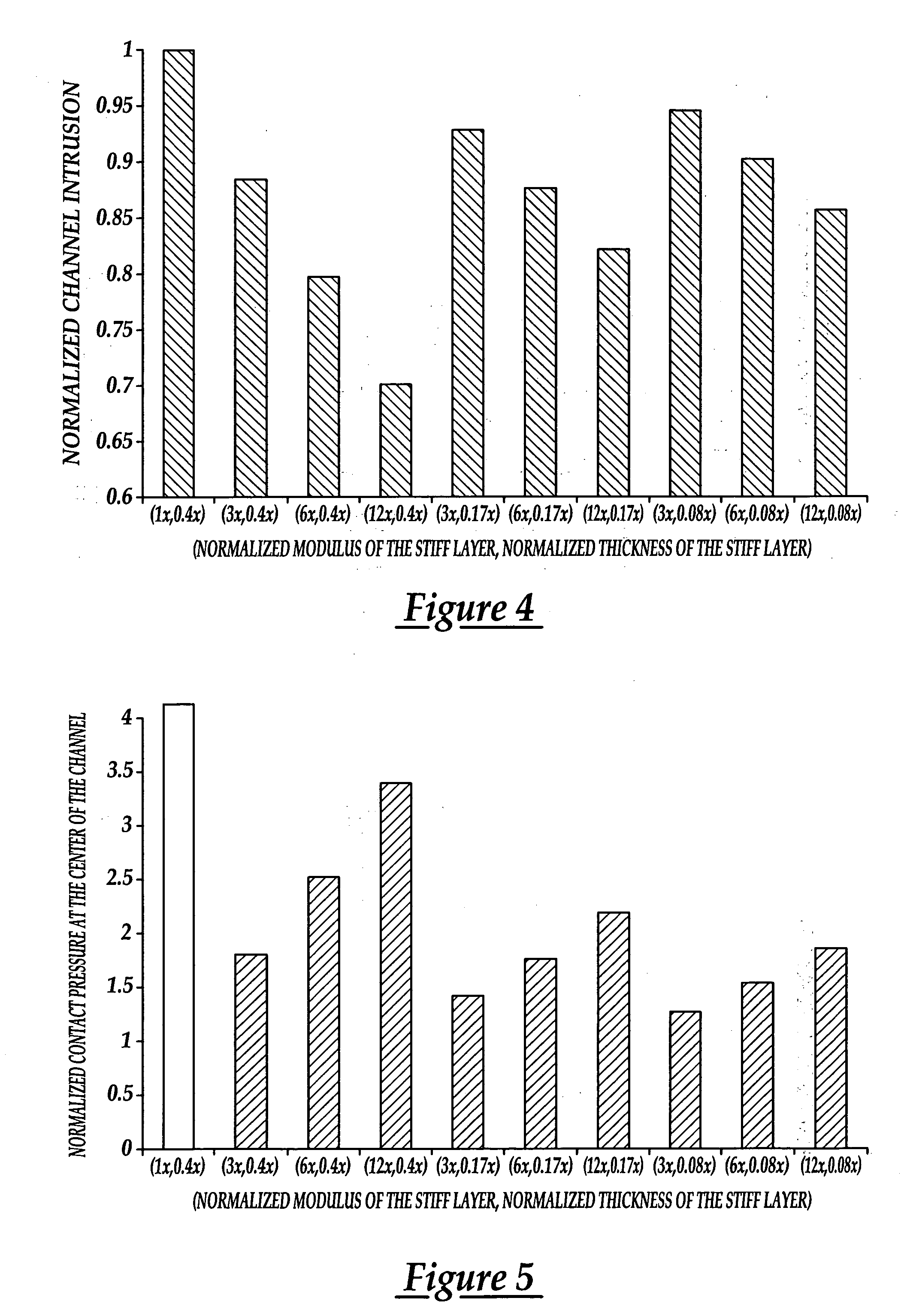
[0030] In FIGS. 4 and 5, a comparison by finite element analysis based computer modeling was performed to evaluate the intrusion and contact pressure at the middle of the channel between the prior-art and the current invention. The prior art is represented by a typical commercial gas diffusion medium (e.g. Sigracet® GDL 21 Series Gas Diffusion Layer by SGL Carbon Group) which was estimated to have a modulus of elasticity of 1000 MPa. The thickness is 260 microns. The behavior of nine multi-layer gas diffusion media variations was modeled, each having the same total thickness as the prior art—260 microns. The compressible layer was assumed to consist of the same material as the prior art. The nine different stiff layers were made of the combination of three thicknesses: 108, 43, and 22 microns and three elasitic moduli of three, six, and twelve times that of the compressible layer. For this illustrative calculation, the z-direction compressibility (i.e., the compressive stress-strain...

example 2

[0031] In addition to the modeling and analysis, a dry pressure drop test was performed in order to exhibit the benefit of the invention with respect to decreasing pressure drop by decreasing diffusion media intrusion into the flowfield channel. In this experiment, the gas diffusion layer to be characterized was placed over the specified flow field, compressed to a given load, and gas was passed through the flowfield at a specified flowrate. This test was performed on a flowfield, and the measured pressure drop in the plate indicated intrusion of the gas diffusion layer into the flow field channel. In the prior art experiment performed, a gas diffusion layer, Freudenberg FC H2315, 209 microns thick, 0.32 strain at 450 psi, 800 MPa modulus of elasticity was used to compare to the invention. The invention was exemplified by placing first a piece of Toray TGPH 030, 105 microns thick, 0.28 strain at 450 psi, 3000 MPa modulus of elasticity) against the flow field, and subsequently placin...


PUM

PropertyMeasurementUnit
Fractionaaaaaaaaaa
Thicknessaaaaaaaaaa
Thicknessaaaaaaaaaa

Abstract

A multi-layer diffusion medium substrate having improved mechanical properties is disclosed. The diffusion medium substrate includes at least one stiff layer and at least one compressible layer. The at least one stiff layer has a greater stiffness in the x-y direction as compared to the at least one compressible layer. The at least one compressible layer has a greater compressibility in the z direction. A method of fabricating a multi-layer diffusion medium substrate is also disclosed.

Description

FIELD OF THE INVENTION [0001] The present invention relates to fuel cells and devices that generate electricity to power vehicles or other machinery. More particularly, the present invention relates to applying a multi-layered gas diffusion medium substrate between a membrane electrode assembly (MEA) and a flow field having a relatively soft and elastic compressible layer which is positioned in proximity to the MEA and a stiff layer which is positioned in proximity to the flowfield. This construction achieves optimum mechanical integrity of the gas diffusion medium and results in optimum performance of the fuel cell. BACKGROUND OF THE INVENTION [0002] Fuel cell technology is a relatively recent development in the automotive industry. It has been found that fuel cell power plants are capable of achieving efficiencies as high as 55%. Furthermore, fuel cell power plants emit only heat and water as by-products. [0003] A fuel cell includes three components at its core: a cathode catalyst...

Claims


Application Information

Patent Timeline
IPC IPC(8): H01M4/94H01M4/96H01M4/88B32B9/00B05D5/12B32B7/022
CPCB32B3/30B32B7/02B32B2262/106B32B2307/51B32B2457/18Y10T428/30H01M4/96H01M8/0234H01M2008/1095Y02E60/50B32B5/26H01M4/8605H01M8/0245B32B7/022
Inventor JI, CHUNXINMATHIAS, MARKO'HARA, JEANETTE E.LAI, YEH-HUNG
Owner GM GLOBAL TECH OPERATIONS LLC
Why Eureka
Try Eureka