Wavelength conversion device

Active Publication Date: 2021-04-15
DELTA ELECTRONICS INC
View PDF0 Cites 1 Cited by
  • Summary
  • Abstract
  • Description
  • Claims
  • Application Information

AI Technical Summary

Benefits of technology

This patent describes a wavelength conversion device that improves heat dissipation efficiency by increasing the thermal conductivity coefficients of thermal conductive plates along the heat transferring path. This reduces the thermal resistance of the heat transferring path, allowing heat generated by the wavelength conversion layer to be efficiently dissipated. The device can be used in various applications such as a reflective wavelength conversion device or a phosphor wheel of a projector. It optimizes the heat transferring path and prevents degradation of conversion performance by effectively dissipating the heat generated during wavelength conversion.

Problems solved by technology

Consequently, the phosphor layer is kept at a high temperature to perform the wavelength conversion and tends to deteriorate, thereby causing the light-emitting rate of the reflective wavelength conversion device to be sharply reduced.
Similarly, the high thermal resistance is formed between the transparent substrate and the heat dissipation device so that the heat dissipation efficiency is reduced.

Method used


Image

  • Wavelength conversion device
  • Wavelength conversion device
  • Wavelength conversion device

Examples


Embodiment Construction

[0043]The present disclosure will now be described more specifically with reference to the following embodiments. It is to be noted that the following descriptions of preferred embodiments of this disclosure are presented herein for purpose of illustration and description only. It is not intended to be exhaustive or to be limited to the precise form disclosed.

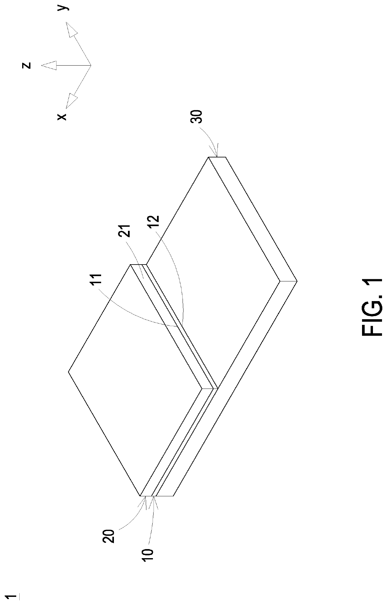
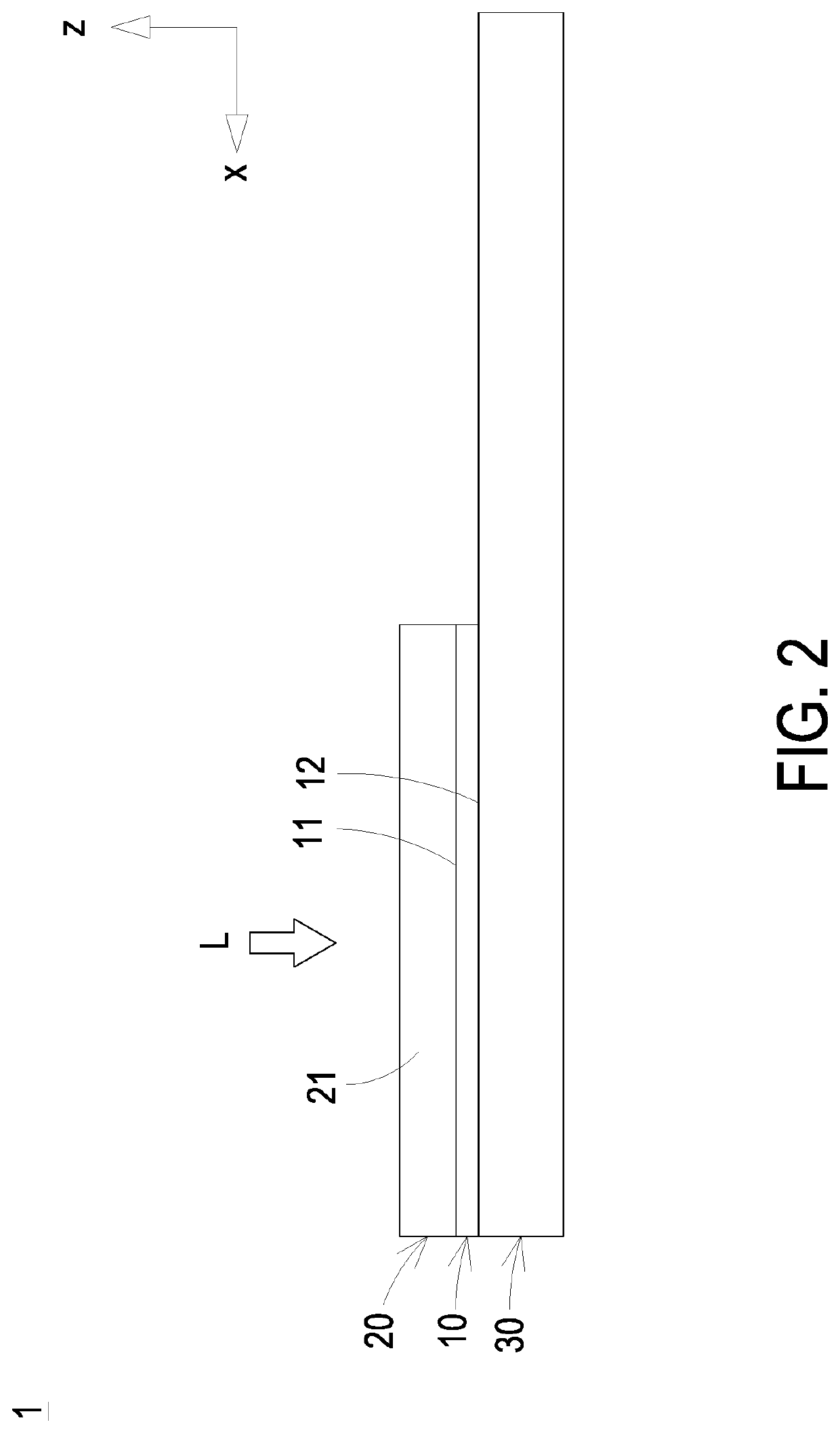
[0044]FIG. 1 is a perspective structural view illustrating a wavelength conversion device according to a first embodiment of the present disclosure. FIG. 2 is a lateral view illustrating the wavelength conversion device of FIG. 1. The wavelength conversion device 1 includes a first thermal conductive plate 10, a wavelength conversion layer 20 and a second thermal conductive plate 30. The first thermal conductive plate 10 includes a first side 11 and a second side 12. The first side 11 is opposite to the second side 12. The interval distance between the first side 11 and the second side 12 is the thickness of the first thermal c...


PUM


Abstract

The present disclosure provides a wavelength conversion device including a first thermal conductive plate, a wavelength conversion layer and a second thermal conductive plate. The wavelength conversion layer is disposed on the first side of the first thermal conductive plate and configured to perform a wavelength conversion. The second thermal conductive plate is disposed on the second side of the first thermal conductive plate. The first thermal conductive plate and the second thermal conductive plate are combined to conduct the heat generated by the wavelength conversion layer during the wavelength conversion. Since the thermal conductivity coefficients of the at least two thermal conductive plates are increased along the heat transferring path, it is advantageous to minimize the thermal resistance of the heat transferring path. Thus, the heat generated by the wavelength conversion layer during the wavelength conversion is dissipated along the heat transferring path to enhance the heat dissipation efficiency.

Description

FIELD OF THE DISCLOSURE[0001]The present disclosure relates to a wavelength conversion device, and more particularly to a wavelength conversion device having a heterogeneous composite board.BACKGROUND OF THE DISCLOSURE[0002]The wavelength conversion device utilizes, for example, a laser light source to excite a phosphor to obtain a predetermined monochromatic or polychromatic light, and has been widely applied in the fields of illumination sources, projection displays, and so on. Taking the projection display as an example, a laser light source is utilized to irradiate the phosphor wheel to produce the desired display color.[0003]In the projection display application, the wavelength conversion device can be distinguished as a reflective type and a transmissive type. Taking the reflective wavelength conversion device as an example, the conventional reflective wavelength conversion device mainly includes a substrate, a reflective layer and a phosphor layer. The reflective layer is dis...

Claims


Application Information

Patent Timeline
IPC IPC(8): F21K9/64
CPCF21K9/64G02B26/008G03B21/204F21V9/30F21V29/503H04N9/3158H04N9/3161H04N9/3144G03B21/16H04N9/3111
Inventor LI, JIH-CHI
Owner DELTA ELECTRONICS INC
Why Eureka
Try Eureka