System and method for controlling ultrasound probe having multiple transducer arrays

a technology of transducer array and ultrasound probe, which is applied in the field of ultrasound medical imaging system probes, can solve the problems of system failure to properly operate, add complexity to the ultrasound system, and may be difficult to operate these ultrasound systems

Inactive Publication Date: 2007-01-18
GENERAL ELECTRIC CO
View PDF39 Cites 34 Cited by
  • Summary
  • Abstract
  • Description
  • Claims
  • Application Information

AI Technical Summary

Benefits of technology

[0006] In an exemplary embodiment, an ultrasound probe is provided that includes a first transducer array and a second transducer array. The ultrasound probe further includes a transducer array selector component within a housing. The transducer array selector component is configured to generate a control signal based on a user input to selectively activate one of the first transducer array and the second transducer array.
[0007] In another exemplary embodiment, an ultrasound probe is provided that includes a first transducer array, a second transducer array and a single system cable for connecting to an ultrasound system. The ultrasound probe further includes a user input device configured to receive a user input and a transducer array selector component within a housing. The transducer array selector component is configured to generate a control signal based on the received user input, with the control signal communicated to the ultrasound system via the single system cable for selectively activating one of the first transducer array and the second transducer array.

Problems solved by technology

If the connections are reversed, the system will not properly operate.
Thus, it not only may be difficult to operate these ultrasound systems because a user has to, for example, turn around to reach the ultrasound system control panel in order to switch between transducer arrays, but the connectors must be properly identified to allow for proper connection of the ultrasound probe to the ultrasound system.
Further, the use of two connectors and corresponding cables not only adds complexity to the ultrasound system, but also adds cost.

Method used


Image

  • System and method for controlling ultrasound probe having multiple transducer arrays
  • System and method for controlling ultrasound probe having multiple transducer arrays
  • System and method for controlling ultrasound probe having multiple transducer arrays

Examples


Embodiment Construction

[0016] Exemplary embodiments of ultrasound systems and methods for controlling ultrasound probes are described in detail below. In particular, a detailed description of exemplary ultrasound systems will first be provided followed by a detailed description of various embodiments of methods and systems for controlling ultrasound probes having multiple transducer arrays.

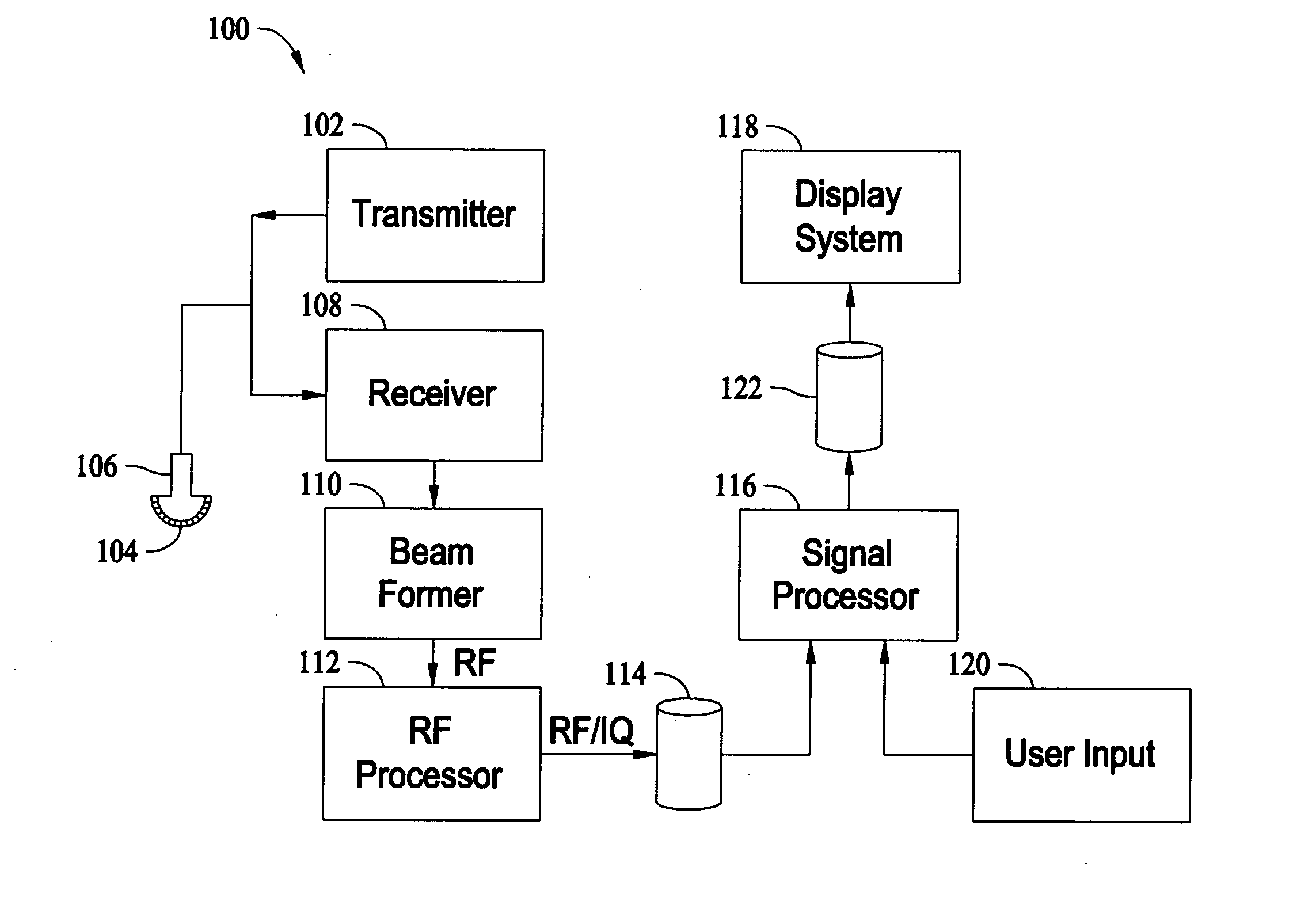
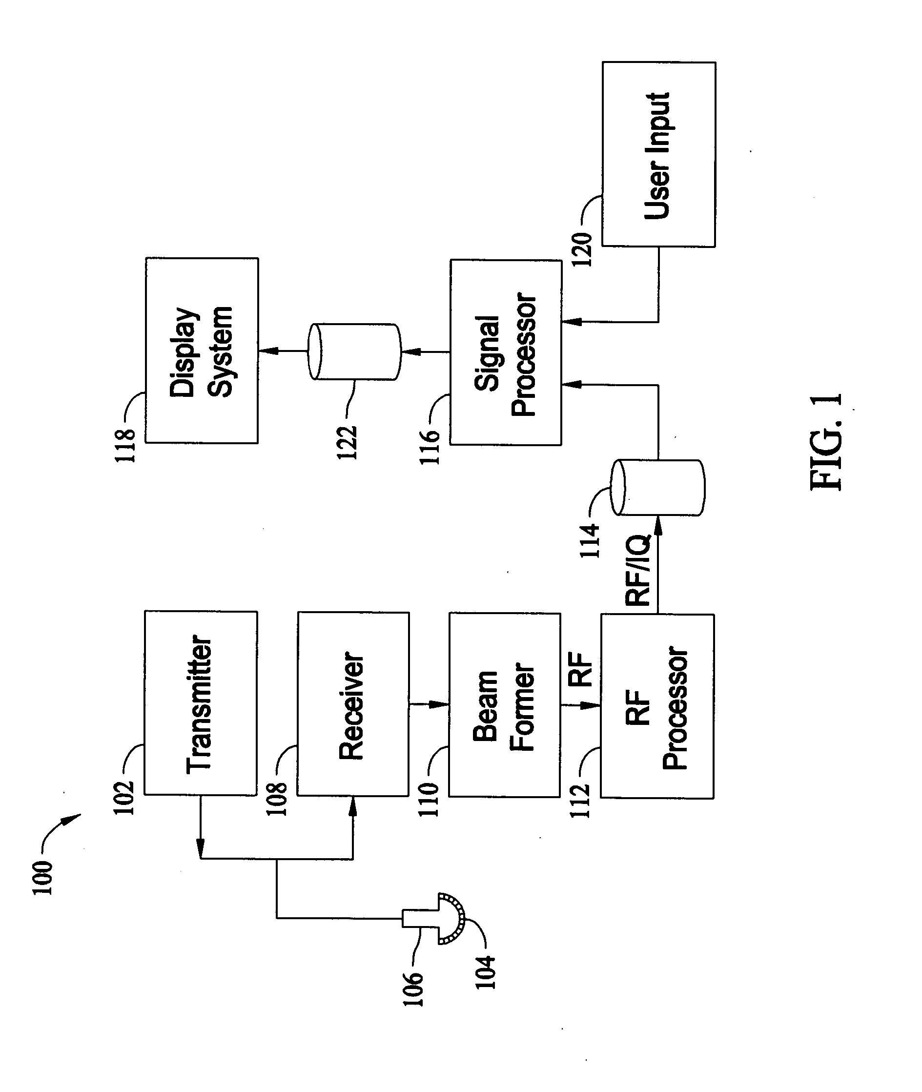
[0017]FIG. 1 illustrates a block diagram of an exemplary embodiment of an ultrasound system 100 that may be used, for example, to acquire and process ultrasonic images. The ultrasound system 100 includes a transmitter 102 that drives one or more arrays of elements 104 (e.g., piezoelectric crystals) within or formed as part of one or more transducers 106 to emit pulsed ultrasonic signals into a body or volume. A variety of geometries may be used and one or more transducers 106 may be provided as part of a probe (not shown) as described in more detail herein. The pulsed ultrasonic signals are back-scattered from density ...


PUM


Abstract

A system and method for controlling an ultrasound probe are provided. The ultrasound probe includes a first transducer array and a second transducer array. The ultrasound probe further includes a transducer array selector component within a housing. The transducer array selector component is configured to generate a control signal based on a user input to selectively activate one of the first transducer array and the second transducer array.

Description

BACKGROUND OF THE INVENTION [0001] This invention relates generally to ultrasound systems and, more particularly, to probes for ultrasound medical imaging systems. [0002] Ultrasound systems typically include ultrasound scanning devices, such as, ultrasound probes having different transducers that allow for performing various different ultrasound scans (e.g., different imaging of a volume or body). The ultrasound probes are typically connected to an ultrasound system for controlling the operation of the probes. The probes include a scan head having a plurality of transducer elements (e.g., piezoelectric crystals), which may be arranged in one or more arrays. The ultrasound system drives the transducer elements within the array during operation, such as, during a scan of a volume or body, which may be controlled based upon the type of scan to be performed. The ultrasound system includes a plurality of channels for communicating with the probe. For example, the channels may transmit pu...

Claims


Application Information

Patent Timeline
Patent Type & Authority Applications(United States)
IPC IPC(8): A61B8/14
CPCA61B8/12A61B8/4488A61B8/467A61B8/483G01S15/8915G01S7/52084G01S15/8925G01S15/8988G01S7/5208A61B8/466
Inventor KERWIN, SCOTT
Owner GENERAL ELECTRIC CO
Why Eureka
Try Eureka