Interference determination method and fmcw radar using the same

a technology of interference determination and fmcw radar, which is applied in the direction of reradiation, measurement devices, instruments, etc., can solve problems such as interference with other radars

Active Publication Date: 2007-01-25
DENSO CORP
View PDF10 Cites 99 Cited by
  • Summary
  • Abstract
  • Description
  • Claims
  • Application Information

AI Technical Summary

Benefits of technology

[0017] The beat frequency of the signal component of the beat signal based on the reflected wave that is a radar wave reflected by a target is high. As illustrated in FIG. 8A, the received power of this reflected wave is reduced with increase in the distance from the target, that is, increase in beat frequency.

Problems solved by technology

When a variation in the sampled data obtained by this sampling exceeds a preset upper limit value, it is determined that interference with some other radar has occurred.

Method used


Image

  • Interference determination method and fmcw radar using the same
  • Interference determination method and fmcw radar using the same
  • Interference determination method and fmcw radar using the same

Examples


Embodiment Construction

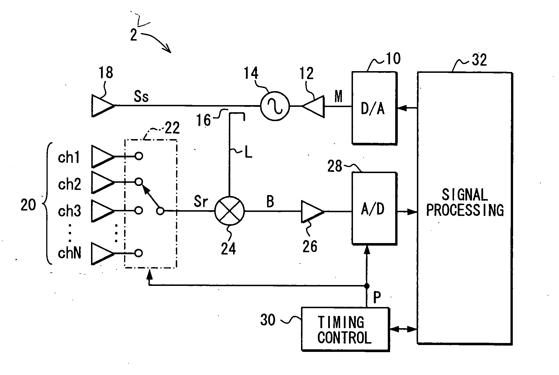
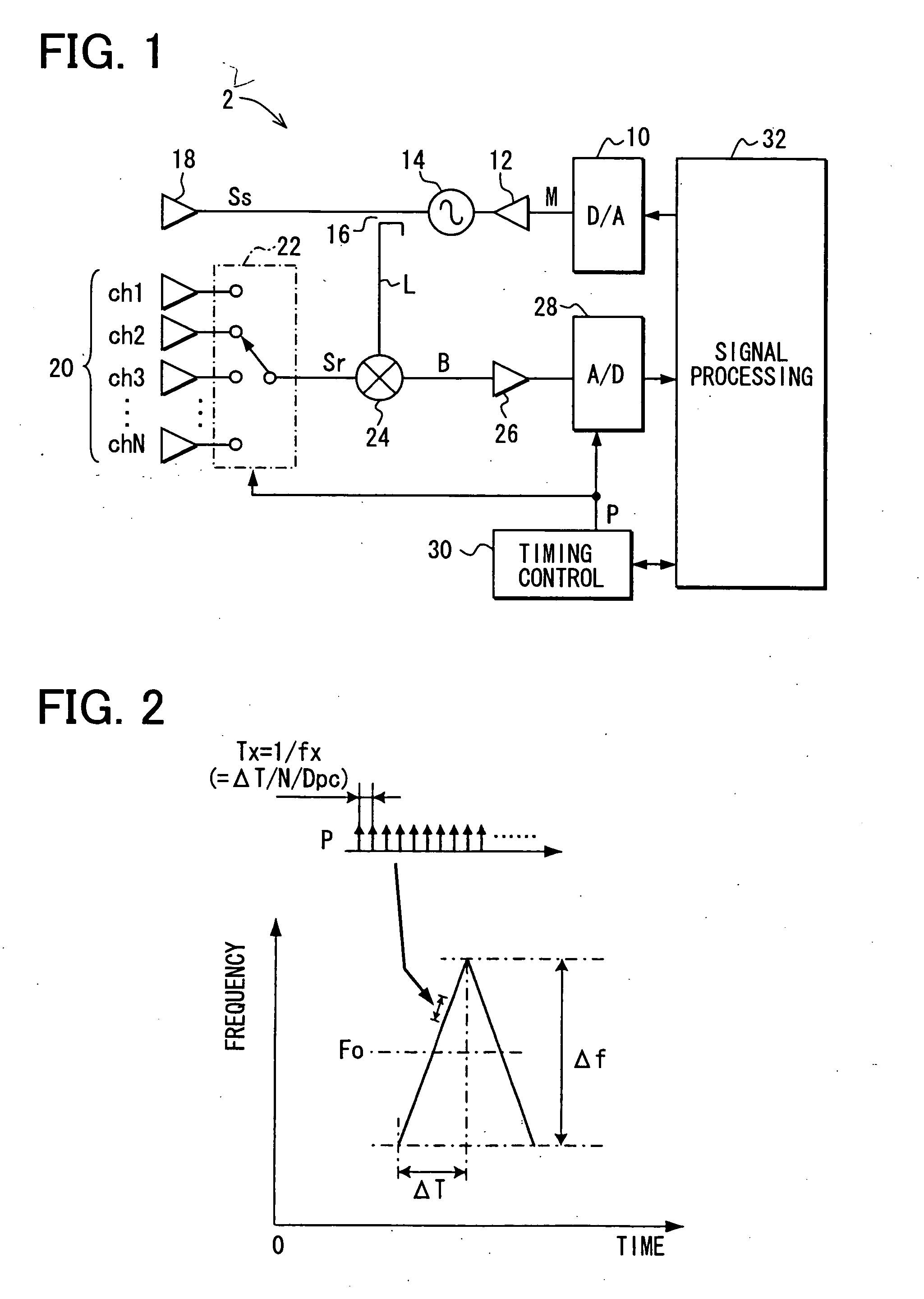
[0042] Referring to FIG. 1, a vehicle-mounted radar 2 includes: a D-A converter 10 that generates a triangular-wave modulating signal M according to a modulation command; a voltage-controlled oscillator (VCO) 14 to which the modulating signal M generated by the D-A converter 10 is applied through a buffer 12 and varies its oscillating frequency according to the modulating signal M; a divider 16 that divides the power of the output of the VCO 14 to a transmission signal Ss and a local signal L; a transmitting antenna 18 that radiates a radar wave corresponding to the transmission signal Ss.

[0043] The radar 2 further includes: a receiving antenna unit 20 constructed of N receiving antennas that receive radar waves; a reception switch 22 that uniquely and sequentially selects any of the antennas of the receiving antenna unit 20 according to a timing signal P, and supplies a received signal Sr from the selected antenna to the subsequent stage; a mixer 24 that mixes the received signal ...


PUM


Abstract

Occurrence of interference is detected using sampled amplitude data obtained by oversampling a beat signal. It is detected by comparing the absolute value (|VD|) of variation in the sampled data with a threshold value (TH). When interference occurs, a wideband signal is superposed on the beat signal, and this disturbs the signal waveform of the beat signal to drastically varies its amplitude. Therefore, occurrence of interference can be detected without fail regardless of the scheme on which a radar as the source of an interference wave is based and even when the amplitude of the interference wave is low. In addition, when low-frequency noise is superposed on the beat signal, erroneous detection of occurrence of interference can be prevented.

Description

CROSS REFERENCE TO RELATED APPLICATION [0001] This application is based on and incorporates herein by reference Japanese Patent Application No. 2005-118498 filed on Apr. 15, 2005. FIELD OF THE INVENTION [0002] The present invention relates to an interference determination method for FMCW radars for determining occurrences of interference between an FMCW radar and some other radar, and an FMCW radar which determines occurrences of interference with some other radars. BACKGROUND OF THE INVENTION [0003] FMCW radars have been conventionally used as one of vehicle-mounted radars to detect any obstacle, a distance to a vehicle ahead, and a relative speed from the vehicle ahead. [0004] The FMCW radar transmits a radar wave frequency-modulated so that its frequency linearly varies with time. It receives a reflected wave that is the radar wave reflected by a target, and mixes the transmission signal and the received signal to generate a beat signal. This beat signal is subjected to frequency...

Claims


Application Information

Patent Timeline
Patent Type & Authority Applications(United States)
IPC IPC(8): G01S7/40G01S7/35G01S13/34G01S13/931
CPCG01S13/345G01S7/023G01S13/931G01S7/0232
Inventor WATANABE, YUUNATSUME, KAZUMA
Owner DENSO CORP
Why Eureka
Try Eureka