Transport of ethernet frames over an sdh network

a technology of ethernet frames and sdh networks, applied in the direction of digital transmission, data switching networks, electrical equipment, etc., can solve the problems of network operators, inability to connect directly to ethernet, costly and complex equipment, etc., and achieve the effect of low degree of complexity and cos

Inactive Publication Date: 2007-01-25
TELEFON AB LM ERICSSON (PUBL)
View PDF5 Cites 11 Cited by
  • Summary
  • Abstract
  • Description
  • Claims
  • Application Information

AI Technical Summary

Benefits of technology

[0006] From what has been described above, it will be realized that there exists a need for a method and a system for the transmission of Ethernet frames between a first and a second LAN which are situated at different geographical sites, which method and system afford a relatively low degree of complexity and cost as compared to present day solutions.

Problems solved by technology

Since the Ethernet technology was originally not conceived for this use, but rather was intended for LAN use at one and the same site, this demand has caused a a problem for network operators.
One of these problems is that Ethernet is a frame based transport technology, while the technologies most frequently used for transporting data between different network locations is based on the continuous transmission of data, by means of the so called Synchronous Digital Hierarchy, (SDH), or the Synchronous Optical NETwork (SONET), usually in combination with and Plesiochronous Digital Hierarchy (PDH).
The PDH technology is often used as an intermediate level between Ethernet LAN:s and the SDH-level or SONET due to the fact that, in most cases, the distance that Ethernet allows data to be transported makes it unfeasible to connect the Ethernet directly to the SDH- or SONET-level, and also due to to the limited penetration of SDH / SONET networks.
Transport of Ethernet frames between two different LAN:s that are geographically separated from one another has thus hitherto been associated with costly and complex equipment for the users, as well as a high degree of network complexity for the operators of the networks.

Method used


Image

  • Transport of ethernet frames over an sdh network
  • Transport of ethernet frames over an sdh network
  • Transport of ethernet frames over an sdh network

Examples


Embodiment Construction

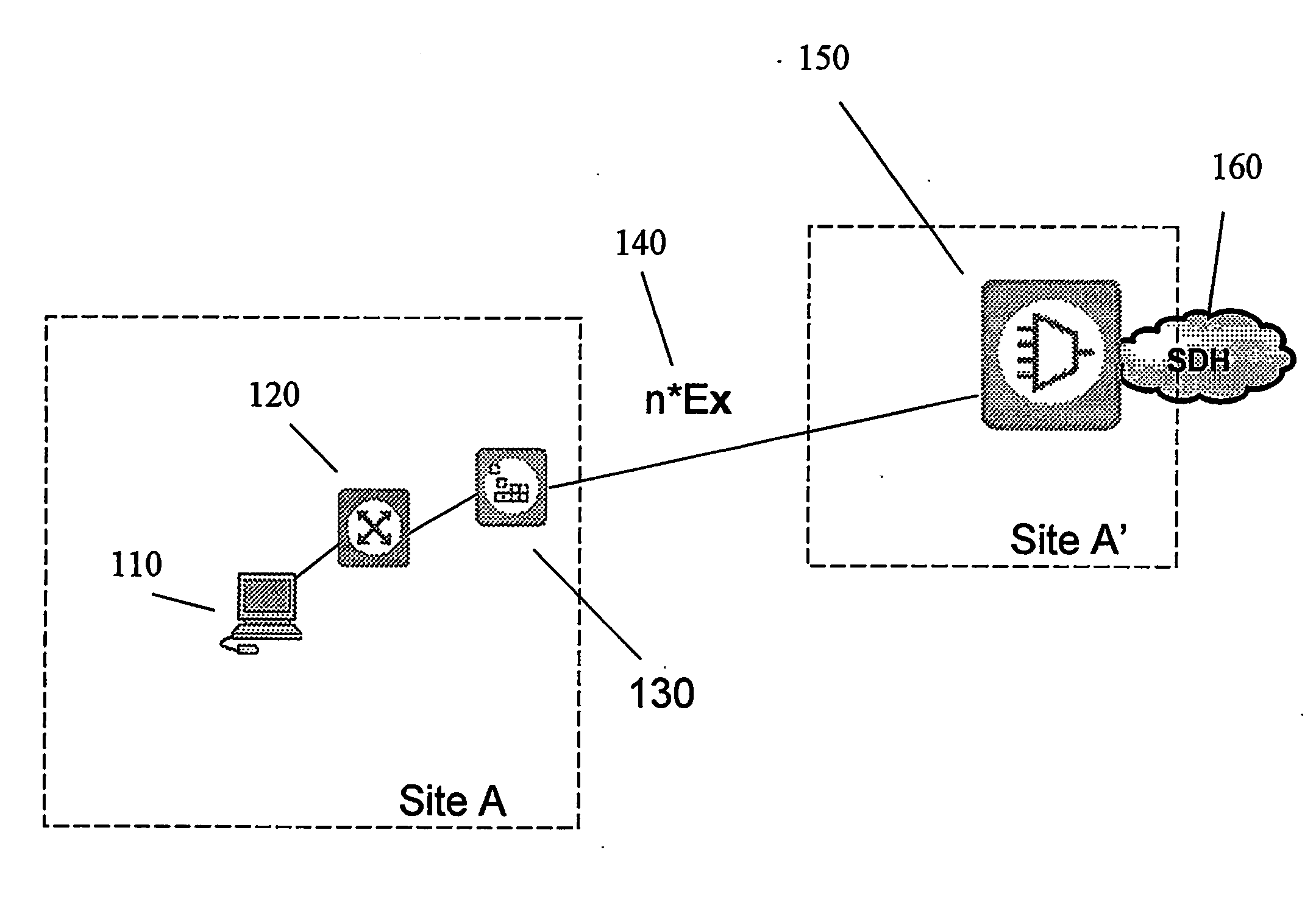
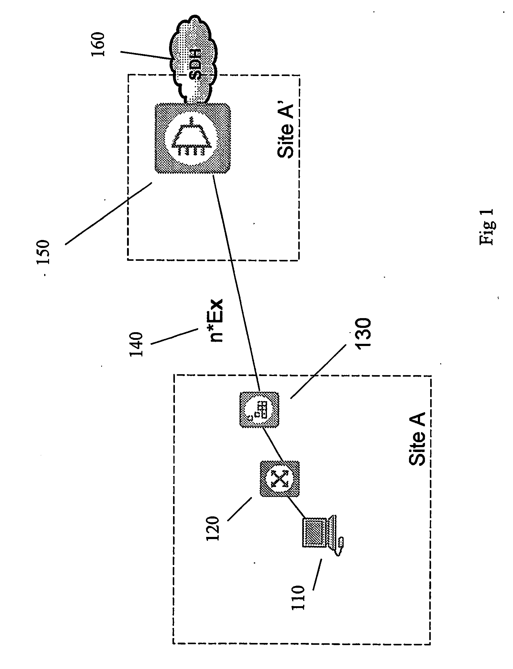
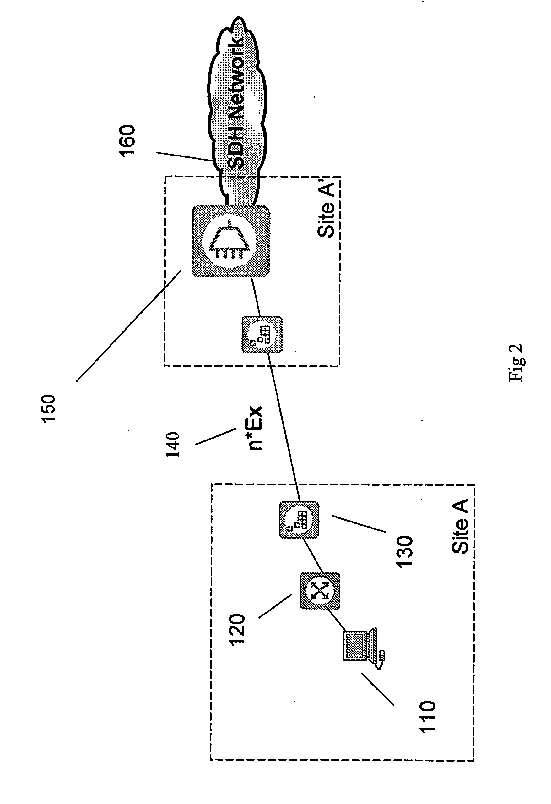
[0015]FIG. 1 shows a first embodiment of a system according to the invention, which system will also operate according to the method of the invention.

[0016] At a first site A, there exists a first Local Area Network, a LAN, 110, which uses the Ethernet protocol. Users within the first LAN 110 at site A wish to be able to communicate not only with each other, but also with the users of a second Ethernet LAN at a second (not shown) site, referred to as B. At an intermediate site A′ there exists an SDH (Synchronous Digital Hierarchy) or SONET network through which the site B may be directly or indirectly reached.

[0017] Due to the distance between sites A and B, it is not feasible to establish direct Ethernet communication between the first and the second site. Instead, use is made of intermediary carriers for transport of the Ethernet frames, first between A and the intermediate site A′: from A, a connection is established to a higher level network 150 at A′ known as an SDH-network (...


PUM


Abstract

The invention refers to a method of transmitting Ethernet data frames from a first local area network (LAN) to a second local area network (LAN) comprising mapping Ethernet frames from the first local area network onto Plesiochronous Digital Hierarchy format via Generic Framing Procedure (GFP) and transmitting the mapped Ethernet frames via a one or multiple En streams to an optional SDH-level network. The transmission is received at the second local area network through the optional SDH-level network via one or multiple En streams-network, and the Ethernet frames are demapped from the first local area network via Generic Framing Procedure, and transmitted into the second local area network.

Description

TECHNICAL FIELD [0001] The present invention relates to the transmission of Ethernet data frames from a first local area network to a second local area network. By means of the invention, such transport is greatly facilitated, in that a plurality of intermediate steps which have been used hitherto can be eliminated. BACKGROUND ART [0002] Local Area Networks (LAN) is a technology that has lately enjoyed a massive success, with the most widely spread transport mechanism in LAN:s being Ethernet. However, as LAN / Ethernet becomes more and more popular, there has arisen a demand from users to be able to connect Ethernet LAN:s at different sites to each other, said sites being geographically separated by large distances, with the user demand being for the ability to establish connection between Ethernet sites separated by more or less arbitrarily large distances. [0003] Since the Ethernet technology was originally not conceived for this use, but rather was intended for LAN use at one and t...

Claims


Application Information

Patent Timeline
Patent Type & Authority Applications(United States)
IPC IPC(8): H04L12/56H04J3/16H04L29/06
CPCH04J3/1617H04L69/08H04J3/1623
Inventor BOLLE, ALDOERIKSSON, ORJAN
Owner TELEFON AB LM ERICSSON (PUBL)
Why Eureka
Try Eureka