Sound field measuring apparatus and sound field measuring method

a technology of measuring apparatus and sound field, applied in the direction of electrical apparatus, stereophonic arrangments, loudspeaker enclosure positioning, etc., can solve the problems of not being fixed, complicated and troublesome adjustment operation of time alignment, and large measurement scale, and achieve the effect of flexible treatmen

Inactive Publication Date: 2007-01-25
SONY CORP
View PDF5 Cites 184 Cited by
  • Summary
  • Abstract
  • Description
  • Claims
  • Application Information

AI Technical Summary

Benefits of technology

[0013] When the above measurement of the sound field is performed, it is possible to select a corrected value of a particular parameter with respect to a local state of frequency of the playback audio signal in the listening environment (peak or dip) or variation of frequency characteristics by using one microphone, and when the equivalent measurement is performed by using plural microphones, and the calculated values are averaged or the like, it is obvious to realize more flexible treatment.

Problems solved by technology

However, in the case that measurement is performed at plural points in the listening environment, the measurement will be large in scale when the number of microphones increases, and the adjustment operation of time alignment is complicated and troublesome for the listener for the reason that the listener has to select where a standard of the time alignment should be and the like.
For the above reason, there is a demand for measuring the playback sound field in the listening environment by fewer numbers of microphones, however, when two microphones are used, for example, the speaker position with respect to the collecting point is not fixed when only the distances between the speaker and the microphones are known.
Since the positional relationship between the both cannot be distinguished on computed values, it was difficult to specify the speaker position accurately.

Method used


Image

  • Sound field measuring apparatus and sound field measuring method
  • Sound field measuring apparatus and sound field measuring method
  • Sound field measuring apparatus and sound field measuring method

Examples


Embodiment Construction

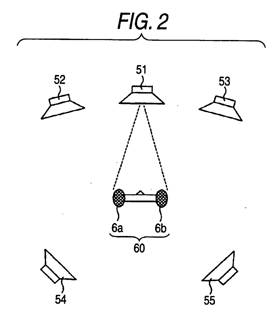
[0045] Hereinafter, a sound field measuring apparatus shown as an embodiment of the invention will be explained in detail with reference to the drawings. The sound field measuring apparatus shown as the embodiment is mounted on an audio set supporting a so-called multichannel system in which plural speakers are connected and a sound field at the time of recording can be realistically reproduced by audio signals outputted from respective speakers, which can accurately measure positional information of respective speakers necessary for analyzing sound field parameters which are given to original audio signals for generating a more realistic sound field.

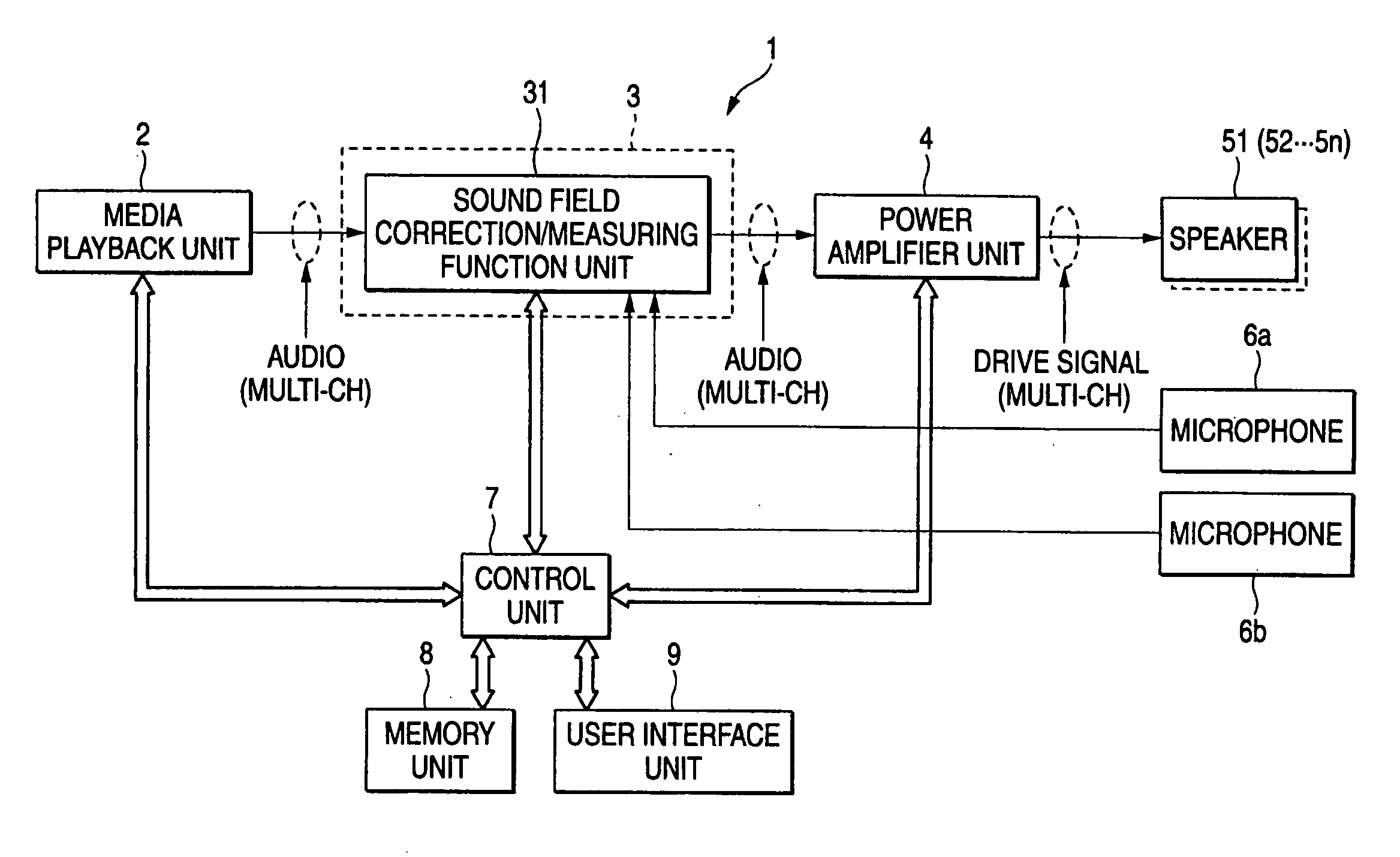
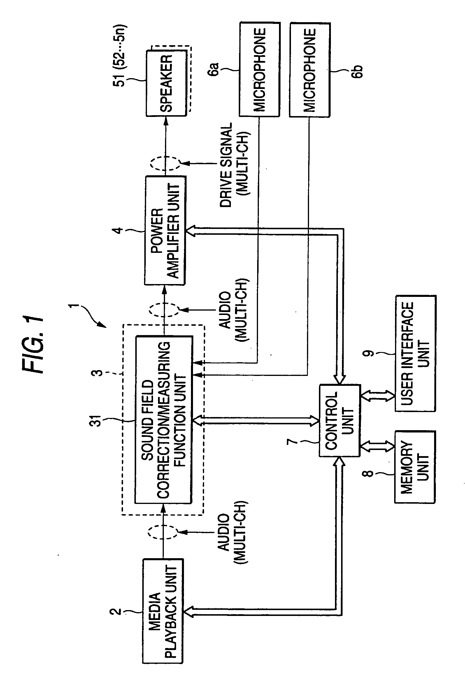
[0046]FIG. 1 shows a structural example of the whole audio set to which the sound field measuring apparatus according to an embodiment of the invention is applied.

[0047] An audio set 1 shown in FIG. 1 includes a media playback unit 2 reading data of musical contents recorded in recording media (hereinafter, referred to as media), a so...


PUM


Abstract

A sound field measuring apparatus includes a microphone set having a first and second microphones arranged at a prescribed interval, which collects audio signals outputted from a first and second speakers, a measuring unit measuring distances between the first and second speakers, and the first and second microphones based on audio signals collected by the first and second microphones, and a position calculating unit calculating a position of the first and second microphones and a position of the second speaker when the first speaker is taken as a standard position based on the respective measured distances.

Description

CROSS REFERENCES TO RELATED APPLICATIONS [0001] The present invention contains subject matter related to Japanese Patent Application JP 2005-210431 filed in the Japanese Patent Office on Jul. 20, 2005, the entire contents of which being incorporated herein by reference. BACKGROUND OF THE INVENTION [0002] 1. Field of the Invention [0003] The invention relates to a sound field measuring apparatus and a sound field measuring method capable of calculating positional relationship of speakers in real space as output means for forming, for example, a multichannel audio system. [0004] 2. Description of the Related Art [0005] In playback systems of video data, musical data and the like, it is relatively easy for users to evaluate realistic sensation or sound quality as good or not good. For example, when a user listen to an orchestral piece, it is preferable that a sound field can be generated, in which the user can sense positions of respective instruments clearly and can recall an image as...

Claims


Application Information

Patent Timeline
Patent Type & Authority Applications(United States)
IPC IPC(8): H04R29/00
CPCH04R2205/024H04R29/00
Inventor ASADA, KOHEIITABASHI, TETSUNORI
Owner SONY CORP
Why Eureka
Try Eureka