Load balancing of server clusters

a server cluster and load balance technology, applied in the field of distributed computer networks, can solve problems such as not having the most beneficial priority cod

Active Publication Date: 2009-07-23
ADOBE SYST INC
View PDF17 Cites 28 Cited by
  • Summary
  • Abstract
  • Description
  • Claims
  • Application Information

AI Technical Summary

Benefits of technology

[0015]The present invention is directed to a system and method for balancing the load of a server cluster in a loosely coupled fashion. By loosely coupling the server cluster, the system and method of various embodiments of the present invention allow for a robust server cluster that can flexibly handle various situations in which servers in the cluster are added, go down, or are fully loaded or approaching a full load. The representative server clusters using the embodiments of the load balancing scheme also provide efficient balancing of applications that benefit from connection stickiness.
[0019]If the preferred server is completely unavailable, either because it is down or has reached its maximum load, the client will still select the server based on the most beneficial priority code that is received during the window. However, because the preferred server is down or is fully loaded, it will not have transmitted its priority code. Thus, the client will still be serviced by one of the available servers without too much delay. The combination of these procedures results in a robust balancing mechanism that flexibly handles all server situations, from adding new servers, removing servers, having servers go down, or when servers are becoming congested.

Problems solved by technology

Therefore, even though it is the preferred server, it may not have the most beneficial priority code received by the client during the messaging window.

Method used


Image

  • Load balancing of server clusters
  • Load balancing of server clusters
  • Load balancing of server clusters

Examples


Embodiment Construction

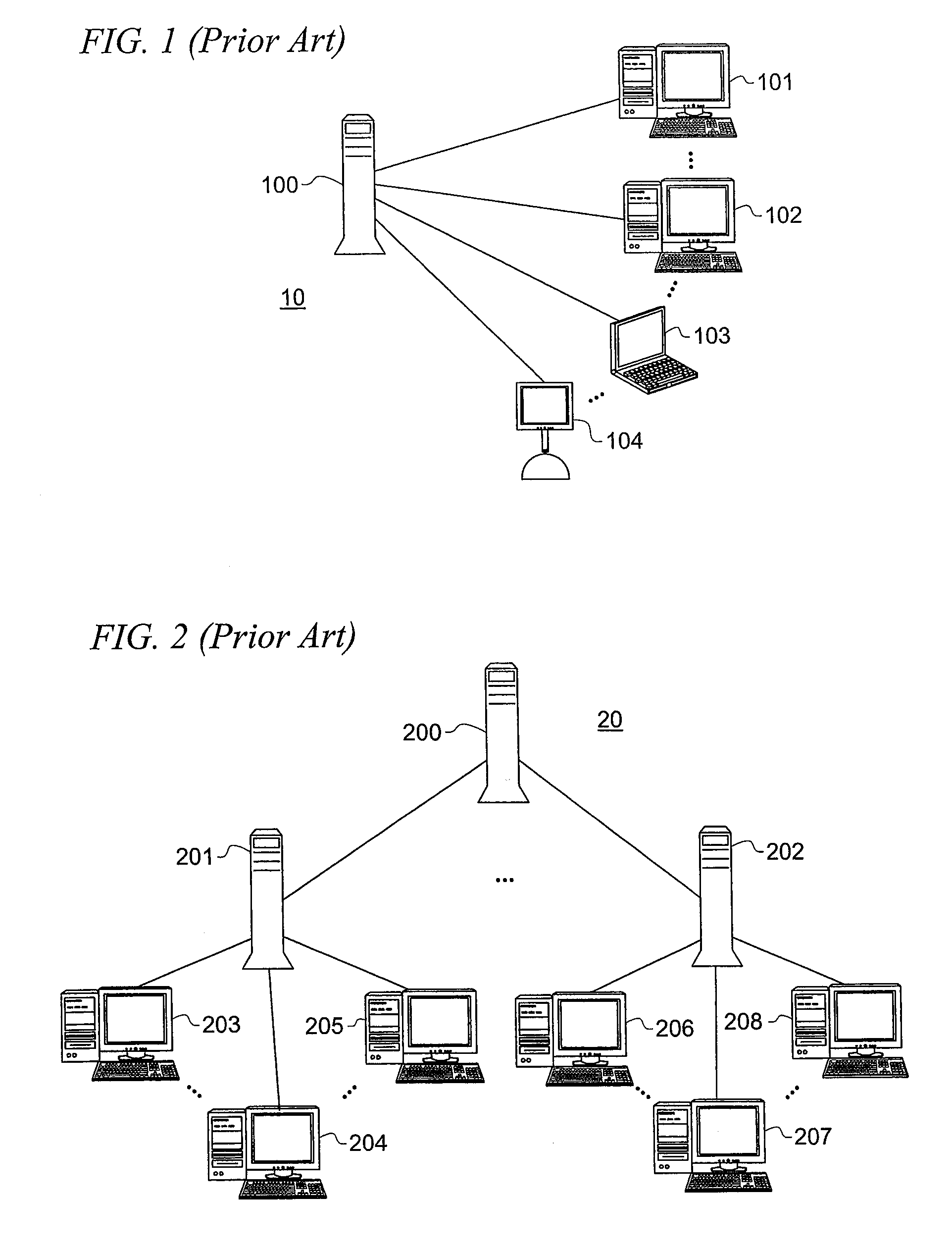
[0029]During the early days of the Internet, its client-server architecture was used as a communications system funded and built by researchers for military use. This Internet, originally known as ARPANET, was embraced by the research and academic communities as a mechanism for scientists to share and collaborate with other scientists. This collaborative network quickly evolved into the information superhighway of commerce and communication that has been a key part of personal and business life in the last 5-10 years. The Internet explosion was due, in part, to the development of the Web and graphically-based Web browsers, which facilitated a more graphically-oriented, multimedia system that uses the infrastructure of the Internet to provide information in a graphical, visual, and interactive manner that appeals to a wider audience of consumers seeking instant gratification.

[0030]As the technology underlying transmission bandwidth has grown in conjunction with the accessibility to s...


PUM


Abstract

A load balancing scheme is described for a server cluster. An application identifier is received by the cluster from a client desiring to connect to the application. Each one of the servers in the cluster independently hashes the application identifier into a unique number. This unique number is used to determine a preferred one of the servers for the connection. The servers then each calculate a priority code using the unique number, a load level for each server, and / or a node identifier assigned to the servers in the cluster. If the preferred cluster server is available, it transmits its priority code to the client before the other servers transmit their priority codes. Otherwise, each of the available cluster servers transmits their priority codes to the client. The client selects the cluster server with the most favorable priority for making the connection.

Description

CROSS-REFERENCE TO RELATED APPLICATIONS[0001]This application is a Continuation of application Ser. No. 11 / 266,770 “LOAD BALANCING OF SERVER CLUSTERS” filed on Nov. 3, 2005. Application Ser. No. 11 / 266,770 is related to U.S. patent application Ser. No. 11 / 263,652 entitled “NETWORK CONFIGURATION WITH SMART EDGE SERVERS” filed on Oct. 31, 2005.TECHNICAL FIELD[0002]The present invention relates, in general, to distributed computer networks, and, more specifically, to load balancing of server clusters.BACKGROUND[0003]In the realm of computing, the relationship that drives most useful distributed applications is the client-server relationship. The interaction between client and server allows most computing beyond an unconnected, single computer. The client-server relationship defines an architecture in which a user's computer, which may be a personal computer (PC), may be the client machine or entity requesting something from a server, which is the supplying machine or entity. However, a...

Claims


Application Information

Patent Timeline
Patent Type & Authority Applications(United States)
IPC IPC(8): G06F15/173
CPCH04L67/1008H04L67/1023H04L67/1002H04L67/1001
Inventor MANAPRAGADA, SRINIVASSHETTY, PRITHAM
Owner ADOBE SYST INC
Why Eureka
Try Eureka