Joint for prosthesis

a joint and prosthesis technology, applied in the field of prosthesis, can solve the problems of mechanical joints not providing sufficient degree, contact plates generally unsuitable for silicone sleeve prosthesis, and difficult to connect/disconnect, etc., to achieve the effect of reducing and/or minimizing electrical noise, and easy connection/disconnecting

Inactive Publication Date: 2007-01-25
BLOORVIEW KIDS REHAB A CORP REGISTERED UNDER THE ONTARIO CORPS ACT
View PDF12 Cites 52 Cited by
  • Summary
  • Abstract
  • Description
  • Claims
  • Application Information

AI Technical Summary

Benefits of technology

[0008] Aspects include a novel children's upper-limb prosthesis. In one aspect, the prosthesis can be fit onto a young child has been successfully fit using a silicone liner and remote electrodes. The prosthesis can overcome or mitigate a number of prior art limitations, including wire breakage, difficulty of electrode and wire attachment, and difficulty of donning / doffing of the prosthesis because the electrodes were hard-wired across the mechanical connection.
[0009] Embodiments can provide an electromechanical quick-connect attachment that enables the user to easily connect / disconnect the prosthetic shell and hand system to / from the liner, yet still provide mechanical suspension / connection between liner and prosthesis and provides for electrical connection of sensor electrodes with control electronics. Electrical, mechanical and functional issues are addressed in the development of the attachment. Issues included robustness of the connection, reduction and / or minimization of electrical noise, strength and durability of the connection, and ease of use and proper suspension of the prosthesis. The quick-connect prosthesis can be applicable for many control input methods. For adults and children with upper-extremity limb loss, this technology enables the benefits of a prosthesis with a better range of motion than traditional “hard shell” systems.

Problems solved by technology

However, this type of fitting has been problematic for the upper extremity myoelectric application.
One problem with prior art prostheses, at least of this type, is that the mechanical joints must provide a sufficient degree of rotation, while also serving as an electrical joint for a plurality of conductors.
It can provide passive wrist rotation, and centralized, constant friction electrical contact. seen in Otto Bock Quality for Life Catalogue—MYOBOCK Arm Components, 2005, page 6.8 However, this Contact Plate is generally unsuitable for silicone sleeve prostheses because it does not provide the appropriate support to enable both mechanical suspension and electrical connection.
Also, it does not provide for a fixed and stable rotational position about the axis of the prosthetic shell.

Method used


Image

  • Joint for prosthesis
  • Joint for prosthesis
  • Joint for prosthesis

Examples


Embodiment Construction

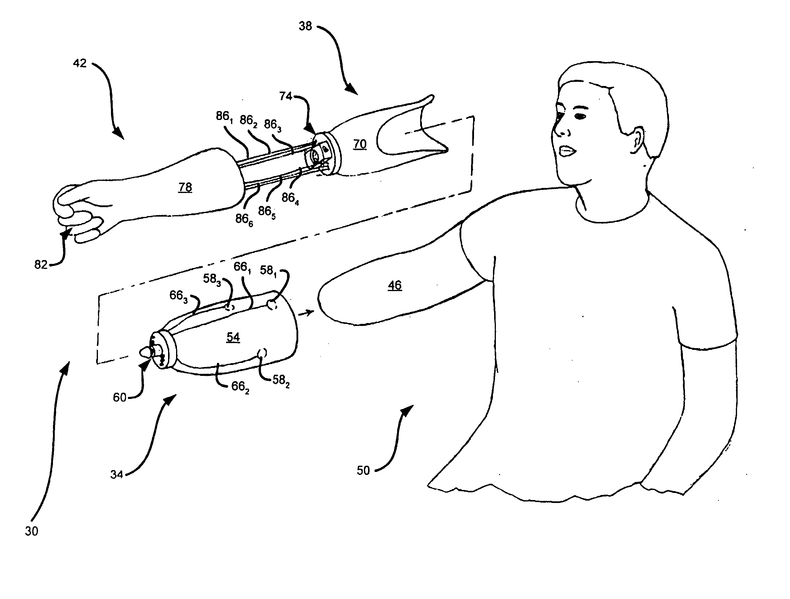
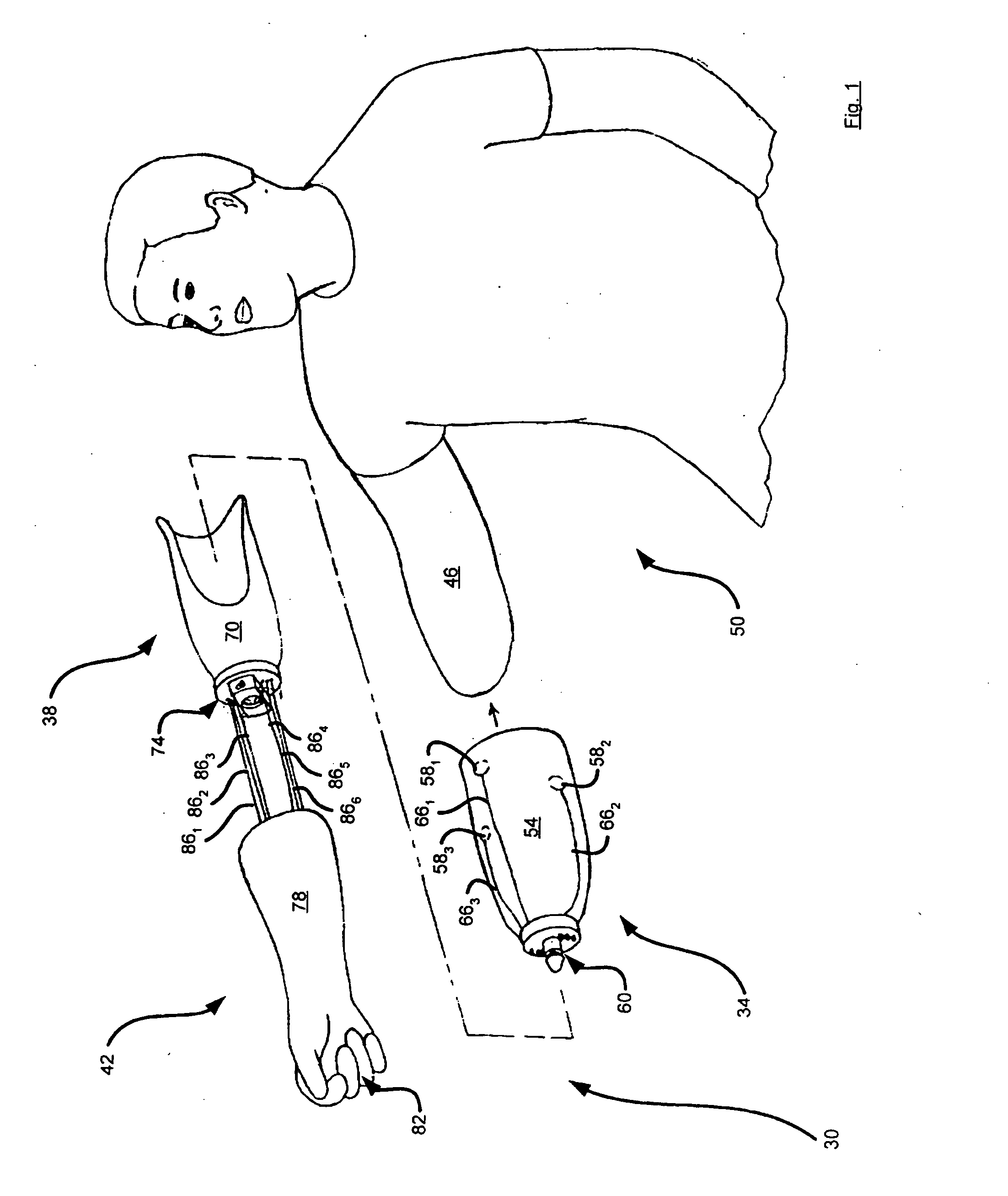
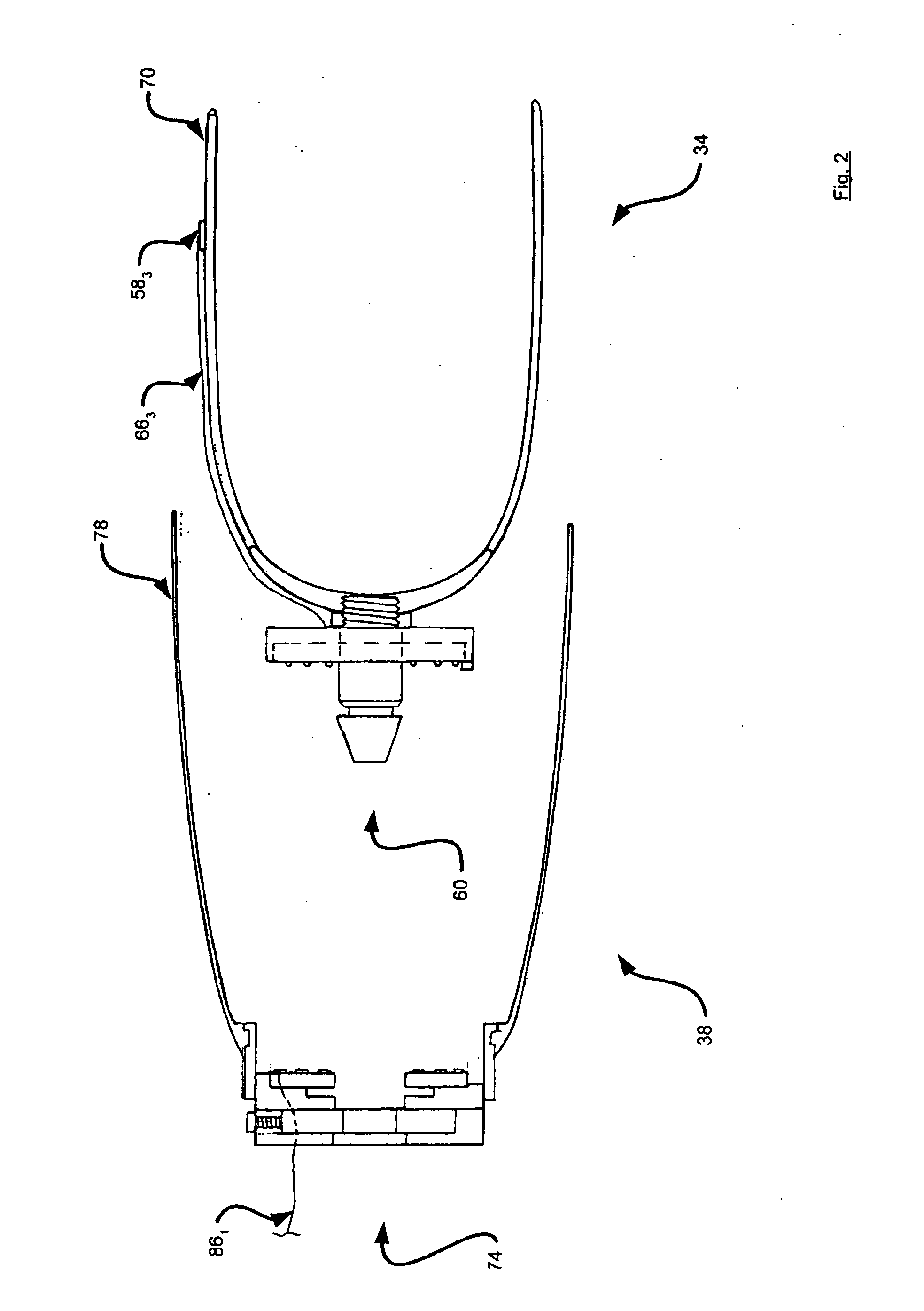
[0021] Referring now to FIG. 1, a prosthesis in accordance with an embodiment of the invention is indicated generally at 30. Prosthesis 30 comprises a liner 34 for complementary engagement with a shell 38. Prosthesis 30 also includes a sleeve 42 which covers shell 38 and liner 34 when prosthesis 30 is assembled and worn on an upper arm 46 of an individual 50.

[0022] As seen in FIGS. 1-3, liner 34 has a hollow body 54 for receiving upper arm 46 therein. Body 54 is thus made from any suitable material such as silicone and is shaped for a complementary fit over upper arm 46. Three electrodes 581, 582 and 583 are provided along body 54. (Collectively, electrodes 581, 582 and 583 are referred to as electrodes 58, and generically as electrode 58. This nomenclature is used for other components discussed herein.) Electrodes 58 are located along body 54 so that electrodes 58 contact certain tissues on upper arm 46. Such tissues are selected so that individual 50 can deliver biological impuls...


PUM


Abstract

A prosthesis is provided having a joint that allows for substantially quick-connection and quick-disconnection of a shell to a liner. The joint also allows for rotational movement and effects electrical connection and mechanical connection between the shell and the liner during connection of the shell to the liner and maintains the connection throughout rotation of the shell in relation to the liner.

Description

PRIORITY CLAIM [0001] The present application claims priority from U.S. Provisional Patent Application 60 / 664,906, filed Mar. 24, 2005, the contents of which are incorporated herein by reference.FIELD OF THE INVENTION [0002] The present invention relates generally to field prosthetics and more particularly relates to joints for prostheses. BACKGROUND OF THE INVENTION [0003] Prostheses can be an important part of providing greater physical independence for individuals who have lost limbs. Silicone liners have proven to be an effective way to suspend upper and lower-extremity prostheses. However, this type of fitting has been problematic for the upper extremity myoelectric application. More specifically, where an individual has lost a forearm, a prosthesis liner can be fit over the individual's upper arm, and a shell containing the mechanical limb connected to the liner. One problem with prior art prostheses, at least of this type, is that the mechanical joints must provide a sufficie...

Claims


Application Information

Patent Timeline
Patent Type & Authority Applications(United States)
IPC IPC(8): A61F2/72A61F2/80A61F2/54
CPCA61F2/54A61F2/583A61F2/68A61F2/72A61F2220/0033A61F2002/3038A61F2002/704A61F2002/705A61F2002/7875A61F2/80A61F2002/30331A61F2/70
Inventor AL-TEMEN, IHSANWELLS, DAVID L.CHAU, GILLBERT
Owner BLOORVIEW KIDS REHAB A CORP REGISTERED UNDER THE ONTARIO CORPS ACT
Why Eureka
Try Eureka