
Pipe for cable

A cable, linear technology, applied in the field of pipes for cables, which can solve the problems of influence, unsatisfactory welding process, the use of complex devices, etc.

Inactive Publication Date: 2004-06-23
ABB (SCHWEIZ) AG
View PDF4 Cites 0 Cited by
  • Summary
  • Abstract
  • Description
  • Claims
  • Application Information

AI Technical Summary

Problems solved by technology

Likewise, these solutions, while effective, however, also have a detrimental impact in terms of production and field laying costs
[0010] Finally, the process of welding between wires is not entirely satisfactory in itself due to the necessity of welding, typically induction welding, which has its own disadvantages and requires the use of complex and expensive devices, and in view of the large number of joints

Method used


Image

  • Pipe for cable
  • Pipe for cable
  • Pipe for cable

Examples


Embodiment Construction

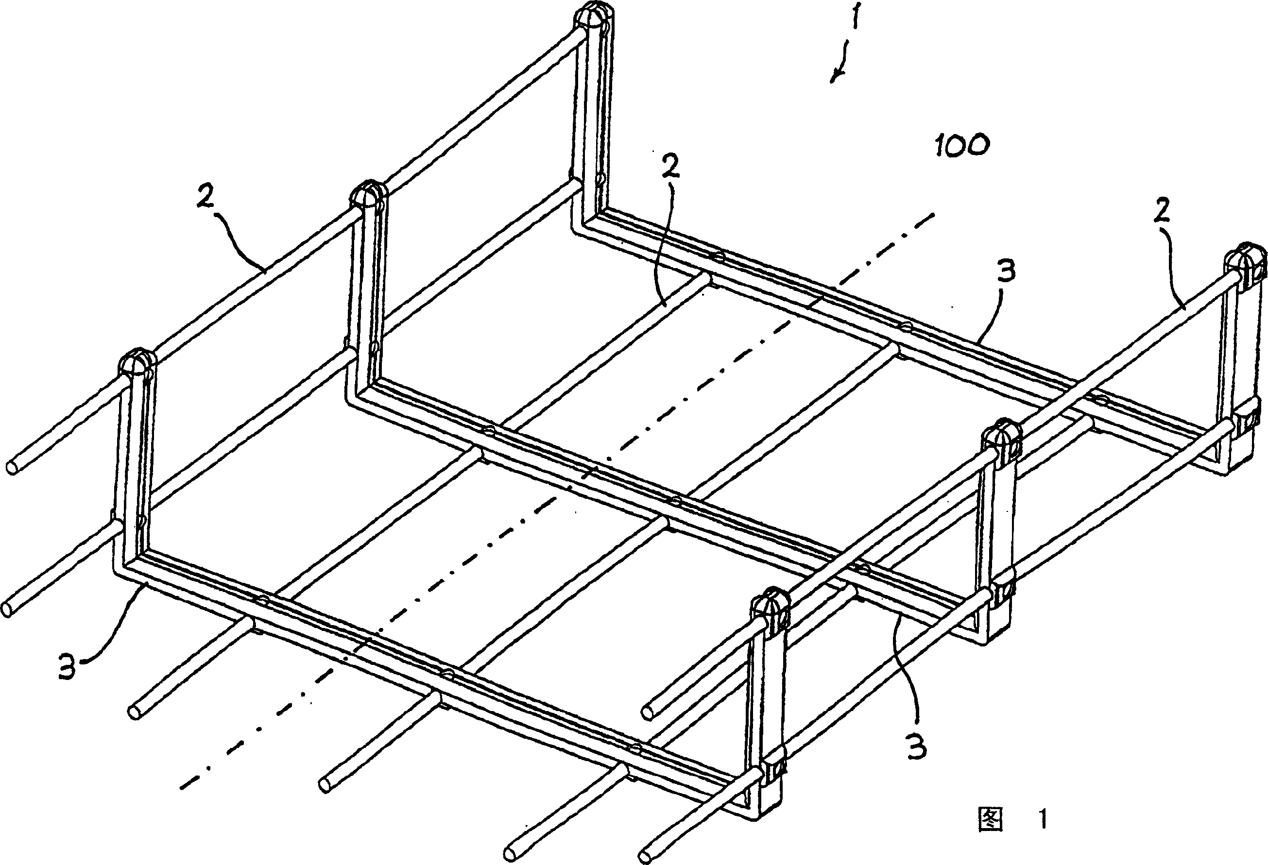
[0022] With reference to the above-mentioned accompanying drawings, the pipe for electric cables of the present invention is indicated by reference numeral 1 as a whole, and it comprises a plurality of linear metal parts 2 placed substantially parallel to each other, which extend longitudinally along the pipe in a straight or similar manner. , the longitudinal direction is represented by axis 100 in FIG. 1 . In the embodiment represented in FIG. 1, the wire-shaped part 2 is generally formed by a metal wire with a circular cross-section, or, in an equivalent manner, the wire 2 can be manufactured with different cross-sections, for example square, rectangular , or other shapes suitable for the application.

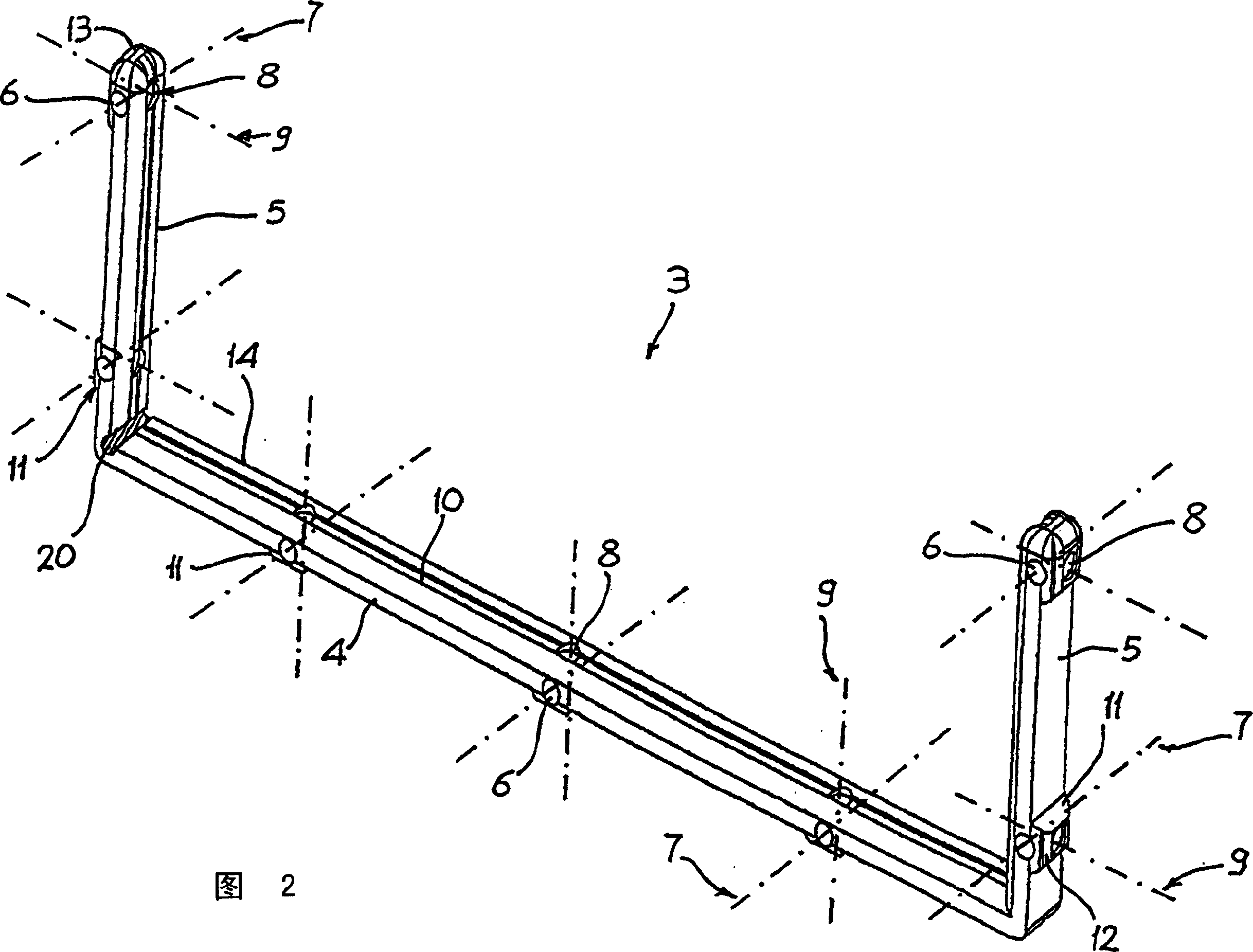
[0023] Preferably, the tube 1 for electrical cables comprises, at least in its longitudinal part length, a plurality of structural components 3, which are operatively connected to the linear part 2 according to the pattern, which will be explained in detail later in the desc...


PUM


Abstract

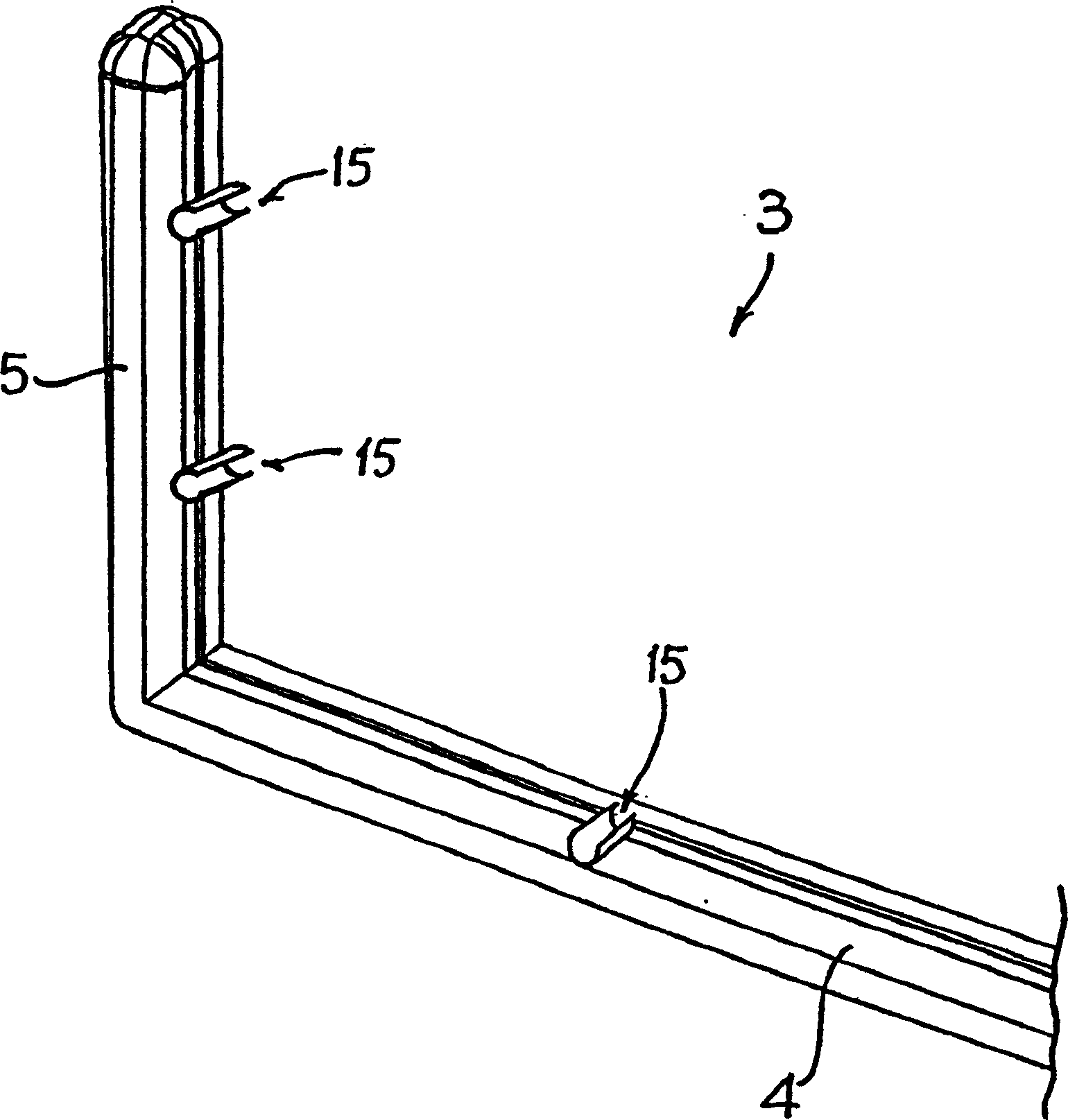
A duct for electrical cables comprises a plurality of filiform metal elements arranged substantially parallel to one another according to the longitudinal development of the duct. The duct of the invention comprises, for at least a portion of its length, a plurality of structural modules, which are arranged in a transverse direction with respect to said filiform elements and are set at a distance from one another in succession according to the longitudinal development of the duct. The supporting modules have a basically U-shaped body that comprises a central wall from which there project, on opposites sides with respect to one another, two side walls that are set substantially parallel to one another. On said shaped body coupling means, designed to enable connection with said filiform elements, are arranged.

Description

technical field [0001] The present invention relates to a tube for electrical cables, in particular a tube, or a cable duct, for electrical cables with improved structure and properties. In particular, the present invention relates to a wire-mesh type of pipe commonly referred to in the art as a wire mesh / cable tray or cable tube, or cable frame. Background technique [0002] As we all know, in some buildings, whether they are used in industry, handicrafts, business or residential areas, such as factories, workshops, hospitals, hotels, residential areas, personal residences, shops, business centers, etc., the current integrated wiring system is more or less It is used in an increasingly wide range of aspects, enabling the transmission of different types of signals to different places in buildings, such as power transmission and distribution, communications, computer systems, various systems for protection and control, and so on. [0003] In these wiring systems, the basic c...

Claims


Application Information

Patent Timeline
Patent Type & Authority Applications(China)
IPC IPC(8): H02G3/04
CPCH02G3/0443
Inventor G·莫里尼R·丰塔纳
Owner ABB (SCHWEIZ) AG
Learn More