Suspension structure for an electric wheelchair

a suspension structure and electric wheelchair technology, applied in the direction of pedestrian/occupant safety arrangement, vehicular safety arrangement, tractors, etc., can solve the problems of electric wheelchairs that have difficulty in getting through barriers, consuming too much power, and risk of tipping, so as to save power consumption of electric wheelchairs of the present invention, the effect of minimizing the bounce of the drive wheels

Inactive Publication Date: 2007-02-01
PIHSIANG MACHINERY MFG
View PDF8 Cites 48 Cited by
  • Summary
  • Abstract
  • Description
  • Claims
  • Application Information

AI Technical Summary

Benefits of technology

[0012] The primary objective of the present invention is to provide a suspension structure for an electric wheelchair, when encountering a barrier, the suspension structure of the present invention can make the front wheel assemblies while pressing the drive wheels downward, thus effectively minimizing the bounce of the drive wheels and making the electric wheelchair move smoothly, furthermore, the power consumption of the electric wheelchair of the present invention is greatly saved.

Problems solved by technology

However, the electric wheelchair will have difficult in getting through a barrier if it is not equipped with good suspension system, and it may have a risk of tipping over.
Although it can overcome a barrier, the conventional wheelchair will consume too much power and cause uncomfortable shock, and the reasons are explained as follows:
First, when encountering a barrier, the drive wheels need to produce a strong driving power for pushing the guide wheel 161 and enabling it to climb up the barrier, however, generating a strong driving power will consume a lot of power.
Second, running on an uneven road, the drive wheels will always bounce up and down without firmly touching the ground, so that the electric wheelchair is unable to move forward stably and smoothly.
Second, when passing a barrier, the cantilevers and the drive rods will bounce up and down under the action of the first and second springs, this cause vibration and make the user feel uncomfortable.

Method used


Image

  • Suspension structure for an electric wheelchair
  • Suspension structure for an electric wheelchair
  • Suspension structure for an electric wheelchair

Examples


Embodiment Construction

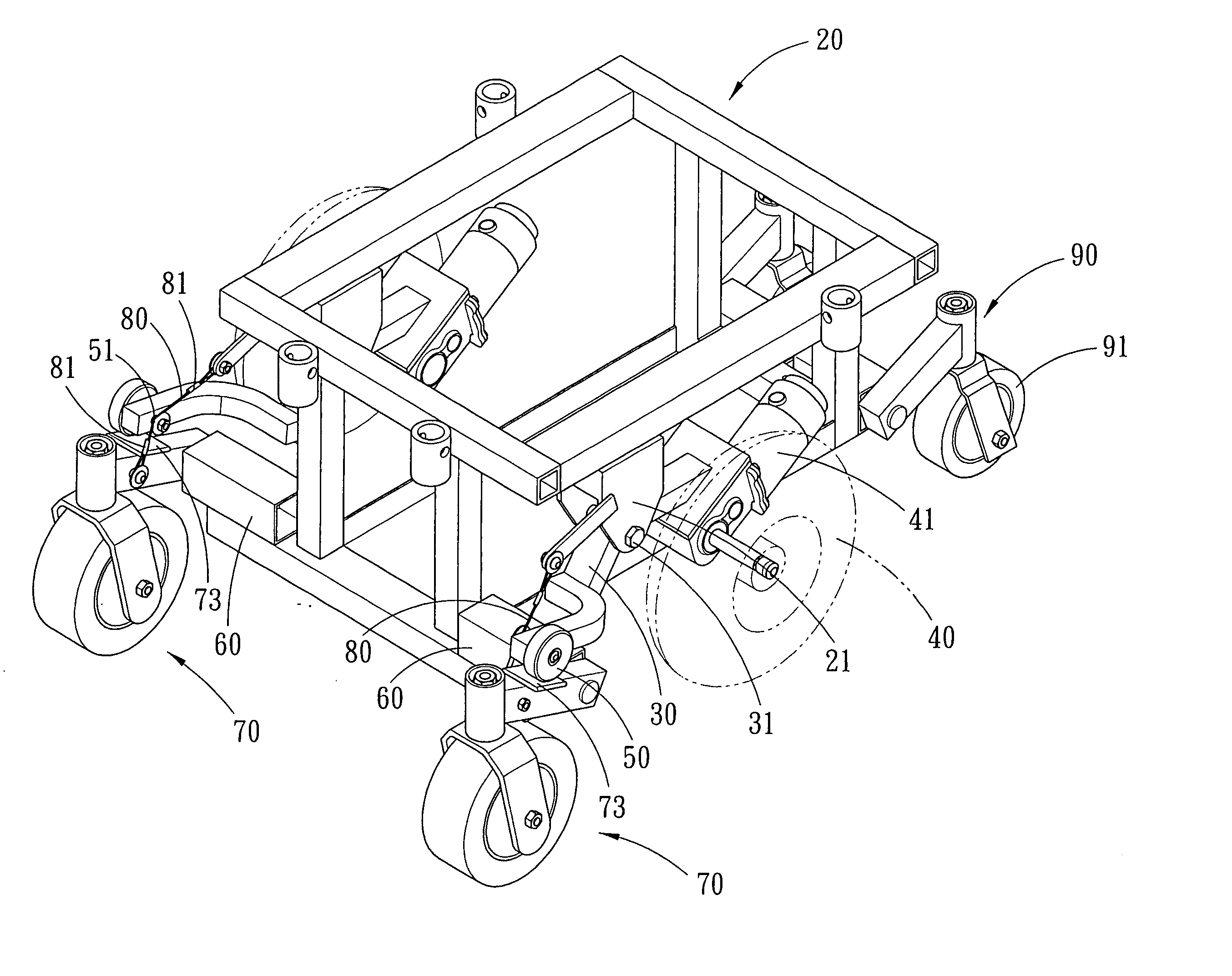
[0023] Referring to FIGS. 3-6, a suspension structure for an electric wheelchair in accordance with the present invention comprises a frame 20, two cantilevers 30, two drive wheels 40, two rollers 50, four wheel-mounting assemblies 60, two front wheel assemblies 70, two draglines 80 and two rear wheel assemblies 90.

[0024] The frame 20 has a pair of ears 21 located at either side of the front portion thereof.

[0025] The respective cantilevers 30 have a mid portion pivoted to the pair of ears 21 of the frame 20, so that the cantilevers 30 can swing about the pivotal point 31.

[0026] The two drive wheels 40 are pivoted to the rear portion of the respective cantilevers 30 and are rotated by a motor 41. By the way, the drive wheels 40 can be located at the center of gravity of the wheelchair and the user, very close to the center of the electric wheelchair.

[0027] The two rollers 50 are fixed pivotally to the outer side of the front end of the respective cantilevers 30 by a pin 51.

[002...


PUM


Abstract

A suspension structure for an electric wheelchair comprises a frame, two cantilevers, two drive wheels, two rollers, four wheel-mounting assemblies, two front wheel assemblies, two draglines and two rear wheel assemblies. When surmounting a barrier, the front wheel assemblies will pivot upward and press down the drive wheels through the cantilevers, thus improving the road holding performance of the drive wheels. In other words, the drive wheels and the front wheels can move interactively to surmount the barrier.

Description

BACKGROUND OF THE INVENTION [0001] 1. Field of the Invention [0002] The present invention relates to a suspension structure for an electric wheelchair, and more particularly to a suspension structure for an electric wheelchair whose mid wheels serving as drive wheels. [0003] 2. Description of the Prior Art [0004] An electric wheelchair is usually used by old age or handicapped people for helping them regain their mobility, and it can move successfully on a smooth road. However, the electric wheelchair will have difficult in getting through a barrier if it is not equipped with good suspension system, and it may have a risk of tipping over. [0005] Referring to FIGS. 1 and 2, a conventional electric wheelchair disclosed by U.S. Pat. No. 6,640,916 is shown, at either side of the frame 10 is arranged a connecting member 11 pivoted to a drive rod 12, and the drive wheel 13 is fixed to the drive rod 12. The drive wheels 13 is driven by a motor 14, between the drive rod 12 and the frame 10 ...

Claims


Application Information

Patent Timeline
Patent Type & Authority Applications(United States)
IPC IPC(8): B60K1/00B62D49/08A61G5/04A61G5/06A61G5/10
CPCA61G5/043A61G5/06A61G2005/1078A61G2005/1089Y10S180/907B60G2204/421B60G2300/24B62D61/12B60G21/045A61G5/1078A61G5/1089
Inventor WU, DONALD P.H.
Owner PIHSIANG MACHINERY MFG
Why Eureka
Try Eureka