Package structure having recession portion on the surface thereof and method of making the same

a packaging structure and recession portion technology, applied in the direction of semiconductor devices, semiconductor/solid-state device details, electrical devices, etc., can solve problems such as failure or product defects, conventional manufacturing methods, etc., and achieve the effect of preventing the bleeding of molding compound and improving product yield

Inactive Publication Date: 2007-02-01
ADVANCED SEMICON ENG INC
View PDF5 Cites 27 Cited by
  • Summary
  • Abstract
  • Description
  • Claims
  • Application Information

AI Technical Summary

Benefits of technology

[0013] The objective of the present invention is to provide a package method, wherein a protruding block is added to the lower mold, and the upper mold and the protruding block respectively clamp the upper and lower surfaces of the first portion of the lead, thus preventing the molding compound from bleeding to the upper surface of the first portion, thereby improving the product yield.

Problems solved by technology

The disadvantage of the conventional fabricating method is described as follows.
As such, during continuous wire bonding operation, the wires 17 cannot be effectively connected to the upper surface 1211 of the first portion 121, thereby causing a failure or product defect.

Method used


Image

  • Package structure having recession portion on the surface thereof and method of making the same
  • Package structure having recession portion on the surface thereof and method of making the same
  • Package structure having recession portion on the surface thereof and method of making the same

Examples


first embodiment

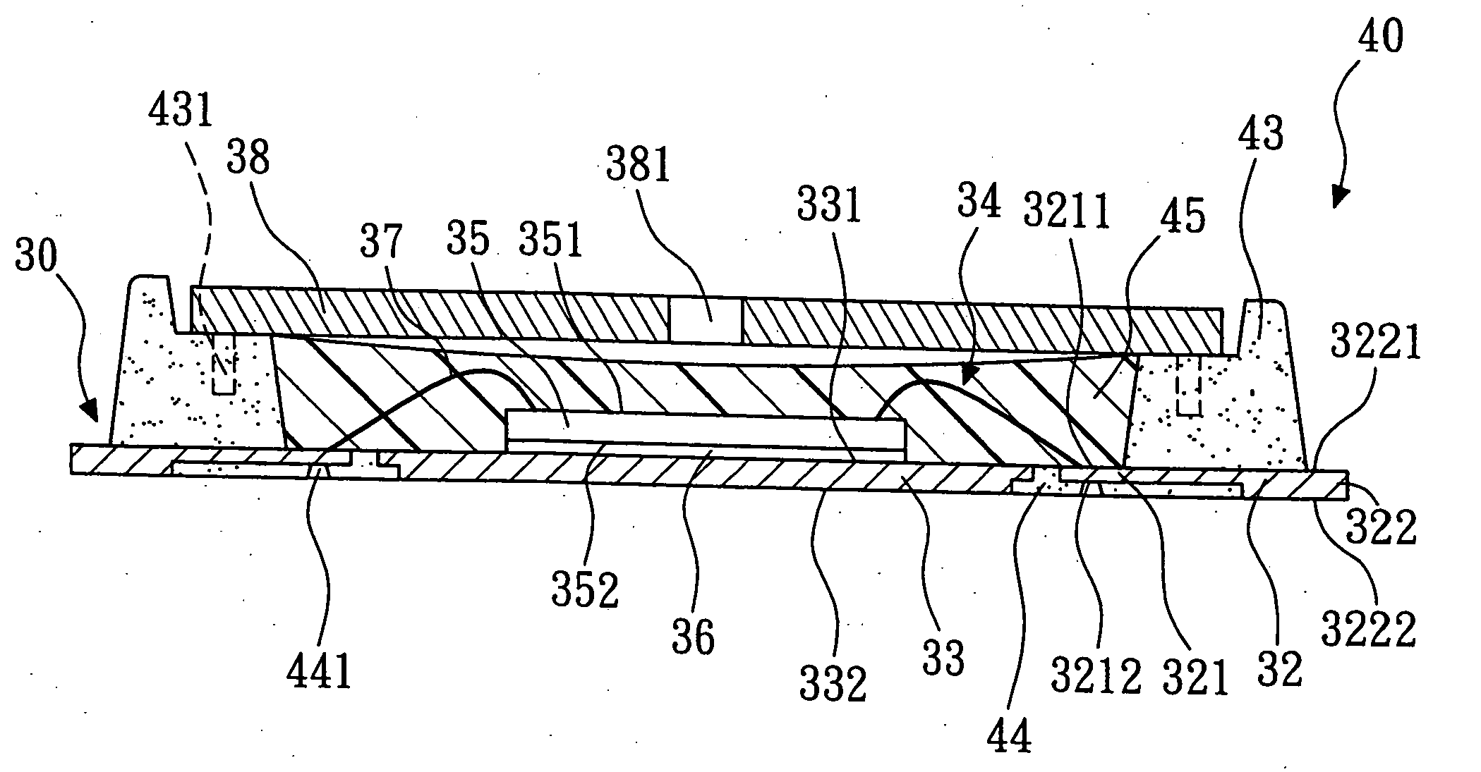
[0036] Referring to FIGS. 5 to 11, the schematic sectional views of the method for making a package structure having a recession portion on the surface according to the present invention are illustrated. First, referring to FIG. 5, a lead frame 30 is provided. The lead frame 30 includes a plurality of package units 31, but only one package unit 31 is illustrated hereinafter. The package unit 31 has a plurality of leads 32 and a die paddle 33, with the leads 32 surrounding the die paddle 33. The die paddle 33 has an upper surface 331 and a lower surface 332. In the embodiment, the upper surface 331 of the die paddle 33 has a plurality of ribs (not shown), for increasing the force for holding the chip. Each lead 32 has a first portion 321 and a second portion 322. The first portion 321 has an upper surface 3211 and a lower surface 3212, and the second portion 322 has an upper surface 3221 and a lower surface 3222. The upper surfaces 3211, 3221 constitute the upper surface of the lead ...

third embodiment

[0057] Referring to FIGS. 15 to 18, a method for fabricating the package structure according to the present invention is illustrated. The fabricating method of the package structure 40B is described as follows. First, referring to FIG. 15, a lead frame 30 is provided. The lead frame 30 has a plurality of package units 31, and each package unit 31 has a plurality of leads 32 arranged circularly. Each of the leads 32 has a first portion 321 and a second portion 322. The first portion 321 has an upper surface 3211 and a lower surface 3212, and the second portion 322 has an upper surface 3221 and a lower surface 3222. The upper surfaces 3211, 3221 form the upper surface of the lead 32, and the lower surfaces 3212, 3222 form the lower surface of the lead 32, wherein the upper surface 3211 of the first portion 321 is used for wire bonding.

[0058] After that, referring to FIG. 16, an upper mold 41 and a lower mold 42 are provided for clamping the lead frame 30. The upper mold 41 presses aga...


PUM


Abstract

The present invention relates to a method for making a package structure having recession portion on the surface thereof. The method comprises: (a) providing a lead frame having a plurality of package units, each package unit having a plurality of leads and a die paddle; (b) providing an upper mold and a lower mold for clamping the lead frame, wherein the upper mold and the protruding block of the lower mold clamp the first portions of the leads so as to prevent molding compound bleeding to the upper surfaces of the first portions during mold filling operation, for improving the product yield; (c) injecting a molding compound between the upper mold and the lower mold, and forming a plurality of accommodation spaces; (d) attaching a plurality of chips onto the die paddles; (e) electrically connecting the chips to the first portions of the leads; (f) sealing the accommodation spaces; and (g) segregating the package units.

Description

BACKGROUND OF THE INVENTION [0001] 1. Field of the Invention [0002] The present invention relates to a package structure and fabricating method thereof, and more particularly to a package structure having at least one recession portion on the lower surface and a method of making the same. [0003] 2. Description of the Related Art [0004] Referring to FIGS. 1 to 4, the schematic sectional views of the method for making a quad flat no-lead package (QFN) with an opening are illustrated. First, referring to FIG. 1, a lead frame 10 is provided. The lead frame 10 includes a plurality of package units 11, but only one single package unit 11 is illustrated hereinafter. The package unit 11 is comprises a plurality of leads 12 and a die paddle 13, wherein the leads 12 surround the die paddle 13, and the die paddle 13 has an upper surface 131 and a lower surface 132. Each lead 12 has a first portion 121 and a second portion 122, wherein the first portion 121 has an upper surface 1211 and a lower...

Claims


Application Information

Patent Timeline
Patent Type & Authority Applications(United States)
IPC IPC(8): H01L23/495
CPCH01L23/24H01L23/49861H01L24/48H01L2224/32245H01L2224/48247H01L2224/73265H01L2924/00H01L2924/181H01L2924/16151H01L2924/16195H01L2924/00014H01L2924/00012H01L2224/45099H01L2224/45015H01L2924/207
Inventor PARK, SANG BAELEE, YONG GILHONG, JIN YOUNGKIM, BAE DOOKIM, SONG WOON
Owner ADVANCED SEMICON ENG INC
Why Eureka
Try Eureka