
Electrical apparatus with voltage drop indicator

a technology of voltage drop indicator and electric apparatus, which is applied in the direction of insulated conductors, cables, instruments, etc., can solve the problems of excessive voltage drop across the cables, system damage, and failure to operate correctly

Inactive Publication Date: 2007-02-01
CLARK RICHARD LEE
View PDF9 Cites 65 Cited by
  • Summary
  • Abstract
  • Description
  • Claims
  • Application Information

AI Technical Summary

Problems solved by technology

If the voltage drop exceeds a predetermined limit, the system will not operate correctly and the system could be damaged.
Due to variations in program material, power amplification, load conditions, and wiring or power block configurations, excessive voltage drop across the cables can affect performance.
With inadequate cables and connectors, a voltage drop occurs as a result of resistive and / or inductive losses.
This voltage drop can manifest itself in degraded audio performance, and in many instances, vehicle performance, as well.
For example, inadequate current for the audio system may result in audio distortion and otherwise less than optimal performance.
Inadequate vehicle current may result in headlights dimming, rough idling, and charging errors.
The disadvantage of this method is that the charts are mere estimates that do not provide an accurate indication of voltage drop in a particular cable or electrical system.
Another method is to use a voltage tester to measure the voltage drop across the cable, but this method requires the purchase of additional equipment and requires an individual to measure the voltage and, in any event, measuring voltage at a particular load may not provide an accurate reflection of system operation under a wide variety of circumstances.

Method used


Image

  • Electrical apparatus with voltage drop indicator
  • Electrical apparatus with voltage drop indicator
  • Electrical apparatus with voltage drop indicator

Examples


Embodiment Construction

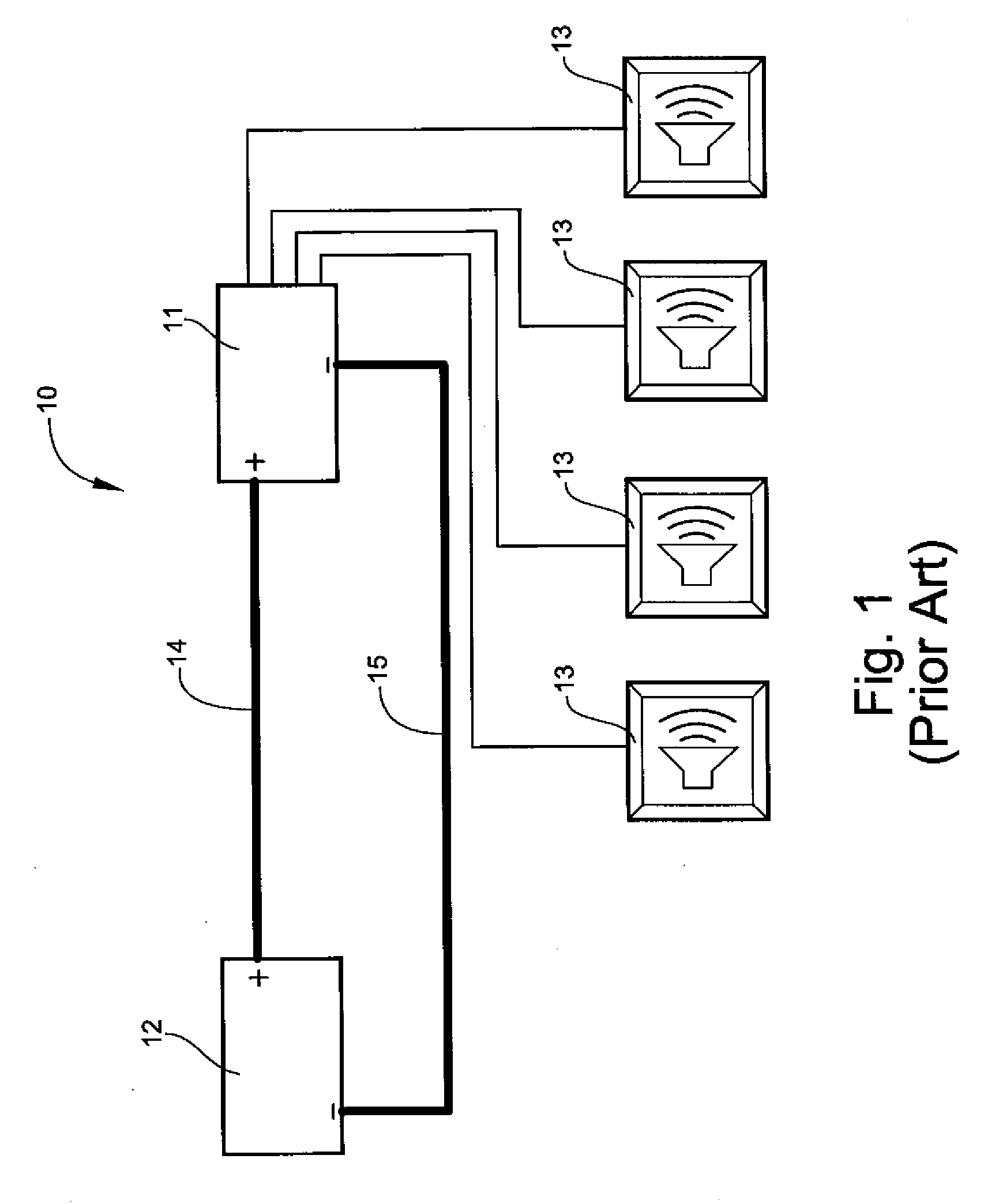
[0058] Referring now specifically to the drawings, a typical prior art mobile audio system is illustrated in FIG. 1 and shown generally at reference numeral 10. The audio system 10 includes an electrical load, such as a power amplifier 11, electrically connected to a power source, such as a battery 12, and a plurality of speakers 13 electrically connected to the amplifier 11. An electrical cable 14 (“power cable”) electrically connects a positive terminal of the battery 12 to a positive terminal of the amplifier 11, and an electrical cable 15 (“ground cable”) electrically connects a negative terminal of the battery 12 to a negative terminal of the amplifier 11. While this discussion is limited to a mobile audio system for illustrative purposes, the present invention is applicable to any electrical system where the voltage drop across an electrical cable or system is of concern, or where constant voltage monitoring is necessary or desirable.

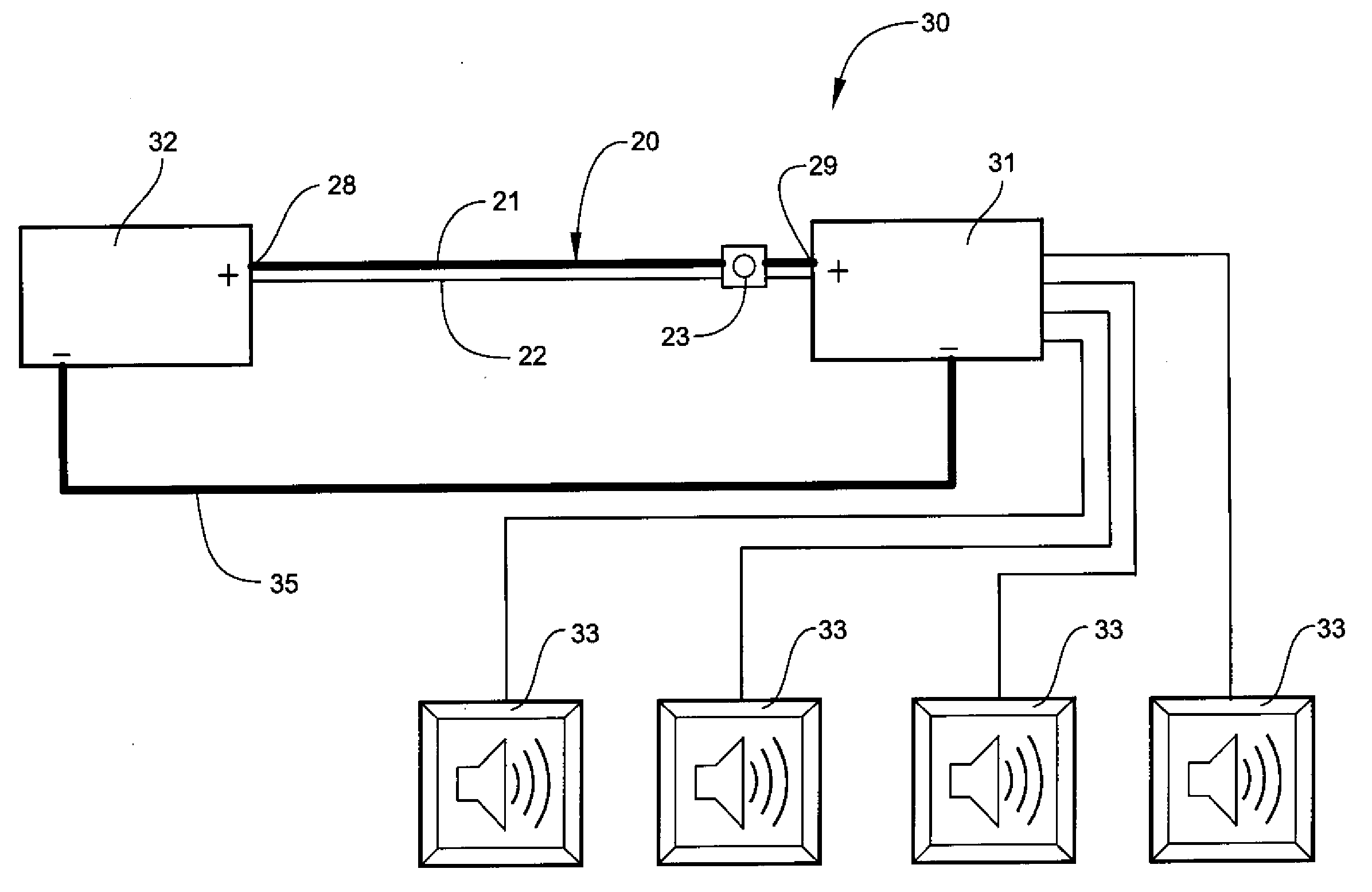
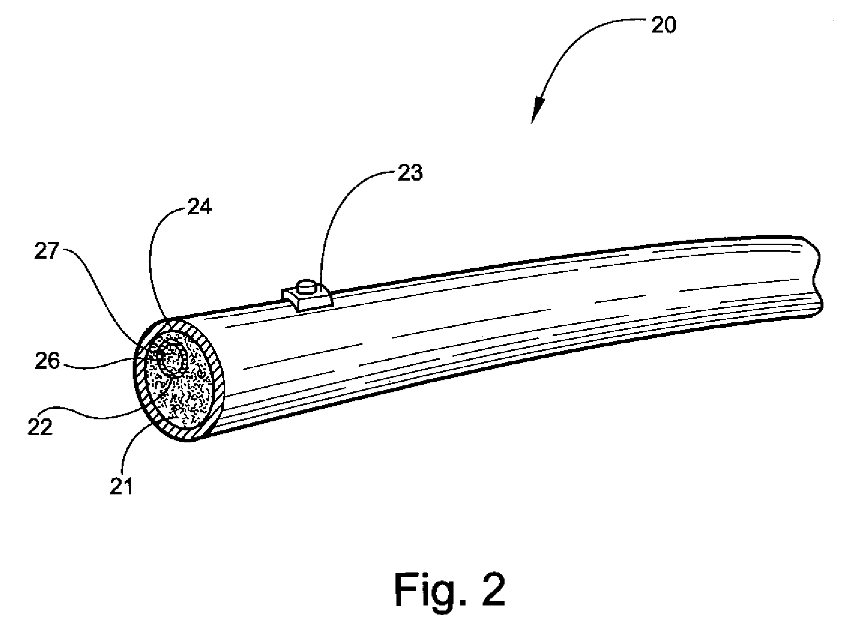
[0059] Referring to FIGS. 2 and 3, an elec...


PUM


Abstract

An electrical apparatus has an indicator for indicating a voltage drop across an electrical system. The electrical apparatus includes a core, a sense lead, and an indicator. The core transmits electrical current from a source to a load. The sense lead electrically connects to the core for sensing a voltage drop between a source end and a sink end of the core. The indicator is operably connected to the sense lead and provides an indication when the voltage drop exceeds a predetermined limit.

Description

CROSS-REFERENCE TO RELATED APPLICATIONS [0001] This application claims the benefit of Provisional Application No. 60 / 595,732 filed on Aug. 1, 2005.TECHNICAL FIELD AND BACKGROUND OF THE INVENTION [0002] The present invention relates to the field of electrical systems. In particular, the invention relates to an electrical apparatus having an indicator for indicating a voltage drop across an electrical system. [0003] In transmitting an electrical current from the power source to the electrical load, it is desirable to supply a current free of distortion and with a minimal voltage drop. In many electrical systems, minimizing voltage drop is very important to the proper operation of the system. This voltage drop usually occurs in the electrical cables and electrical connectors used to electrically connect the power source and load. If the voltage drop exceeds a predetermined limit, the system will not operate correctly and the system could be damaged. [0004] For example, in many contempo...

Claims


Application Information

Patent Timeline
IPC IPC(8): G08B21/00
CPCH02H3/24H01B7/32
Inventor CLARK, RICHARD LEE
Owner CLARK RICHARD LEE
Learn More