This helps you quickly interpret patents by identifying the three key elements:
Problems solved by technology
Method used
Benefits of technology
Benefits of technology
[0018] According to the first aspect of the present invention, since the land portions are arranged such that a certain land portion is shifted, in the longitudinal direction of the pressure chamber, from another land portions which are adjacent to the certain land portion intervening the certain land portion therebetween, the distance (spacing distance) between the land portions is wider than in a case in which the land portions are aligned in a horizontal row (for example, in the short direction of the pressure chambers) Accordingly, in the flexible cable, on the side at which the signal lines are drawn (the signal-line drawn side) and at which the wiring pitch of the signal lines is the narrowest, the signal lines formed as a conductive pattern can be wired, in a non-tight or non-narrow manner (without making the signal lines arranged very narrowly or tightly), between the connection terminals, of the flexible cable, which are to be electrically connected to the land portions. In other words, a space for wiring or drawing the signal lines in the flexible cable is secured reasonably by devising a method for arranging the land portions which are electrically conducted to the individual surface electrodes, respectively, and which are arranged between the individual surface electrodes adjacent to one another. Therefore, without using a plurality of flexible cables (for example, FPC, COP, COF or the like), it is possible to electrically connect the land portions, of the actuator, formed corresponding to the densely arranged pressure chambers, to the connection terminals of the flexible cable, in an easy and inexpensive manner.
[0056] In the ink-jet printer of the present invention, the head may include only one piece of the flexible cable. In this case, since the head of the ink-jet printer does not use a plurality of flexible cables, it is possible to enhance the reliability of the electrical connection and mechanical connection between the land portions and the connection terminals.
Problems solved by technology
In the ink-jet head described in U.S. Pat. No. 7,004,565, however, there is a problem that in a flexible cable (FPC, COF or COP) used for connecting the individual surface electrodes of the actuator unit to a control board, signal lines (a conductive pattern formed on a substrate which is flexible and has insulating property), connected to the adhesion land portions corresponding to the individual surface electrodes, respectively, are concentrated (congested) on a side of the flexible cable at which the signal lines are drawn, thereby increasing the number of signal lines on this side of the flexible cable.
Accordingly, the wiring (line) pitch of the signal lines (conductive pattern) becomes narrow and thus it is difficult to realize a miniaturized head and densified nozzles (nozzles which are arranged highly densely).
That is, when the sizes of the head terminals and the terminal electrodes are reduced to be small, there is a fear that the electrical connection cannot be performed successfully if the head terminals and / or the terminal electrodes are deviated from (moved out of) their positions even by a small amount while performing the connection.
Therefore, in such a wiring construction, the pitch of the signal lines of the flexible cable is still narrow, which in turn makes it difficult to further arrange the nozzles highly densely.
However, the increase in the number of flexible cables not only weakens the mechanical strength of the wiring connection considerably but also increase the production cost.
Method used
Image
Click on the blue label to locate the original text in one second.
Reading with bidirectional positioning of images and text.
Examples
first modified embodiment
[0090] The arrangement of the plurality of land portions constructing each of the groups is not limited to the arrangement in which the land portions are arranged on the straight line L inclined with respect to the longitudinal direction of the pressure chambers 14Aa. For example, the land portions may be arranged as shown in FIGS. 8 to 10.
[0091] In this case, a plurality of land portions 22e, 22f, 22g and 22h constructing each of the groups are arranged one by one at a uniform spacing distance in the longitudinal direction of the pressure chambers 14Aa. Further, in each of the groups, the spacing distance is widest between the land portions 22e and 22h disposed at both ends, respectively, of each of the groups, and the remaining land portions 22f and 22g are not arranged on a straight line connecting the two land portions 22e and 22h. The land portions 22e to 22h in this modified embodiment are arranged in the same way as the land portions 22a to 22d shown in FIGS. 4 to 7 except t...
second modified embodiment
[0093] In the above-described embodiment, each of the group of the individual surface electrodes includes four individual surface electrodes. However, the number of the individual electrodes included in each of the groups is not limited to four, and the number of the individual surface electrodes forming each of the groups may be three, five or not less than five.
third modified embodiment
[0094] Although in the above-described embodiment, the pressure chambers 14Aa include color-designated pressure chambers to which inks of different colors (magenta, cyan, yellow and black) are supplied respectively, there is no limitation to the color of the ink supplied to pressure chambers 14Aa corresponding to individual surface electrodes 21 on the signal-line drawn side at which the signal lines 31 are drawn. In the following case, however, it is desired that pressure chambers to which the black ink is supplied are arranged on the signal-line drawn side.
[0095] Since a large ink discharge amount is generally required for the black ink, the length of pressure chambers 14Aa and the length of manifolds 14Da, 14Ea for the black ink are greater than those for other colors other than black for purpose of the stable ink discharge. In such a case, the length of individual surface electrodes 21 formed corresponding to the pressure chamber 14Aa for the black ink is greater than the lengt...
PUM
Abstract
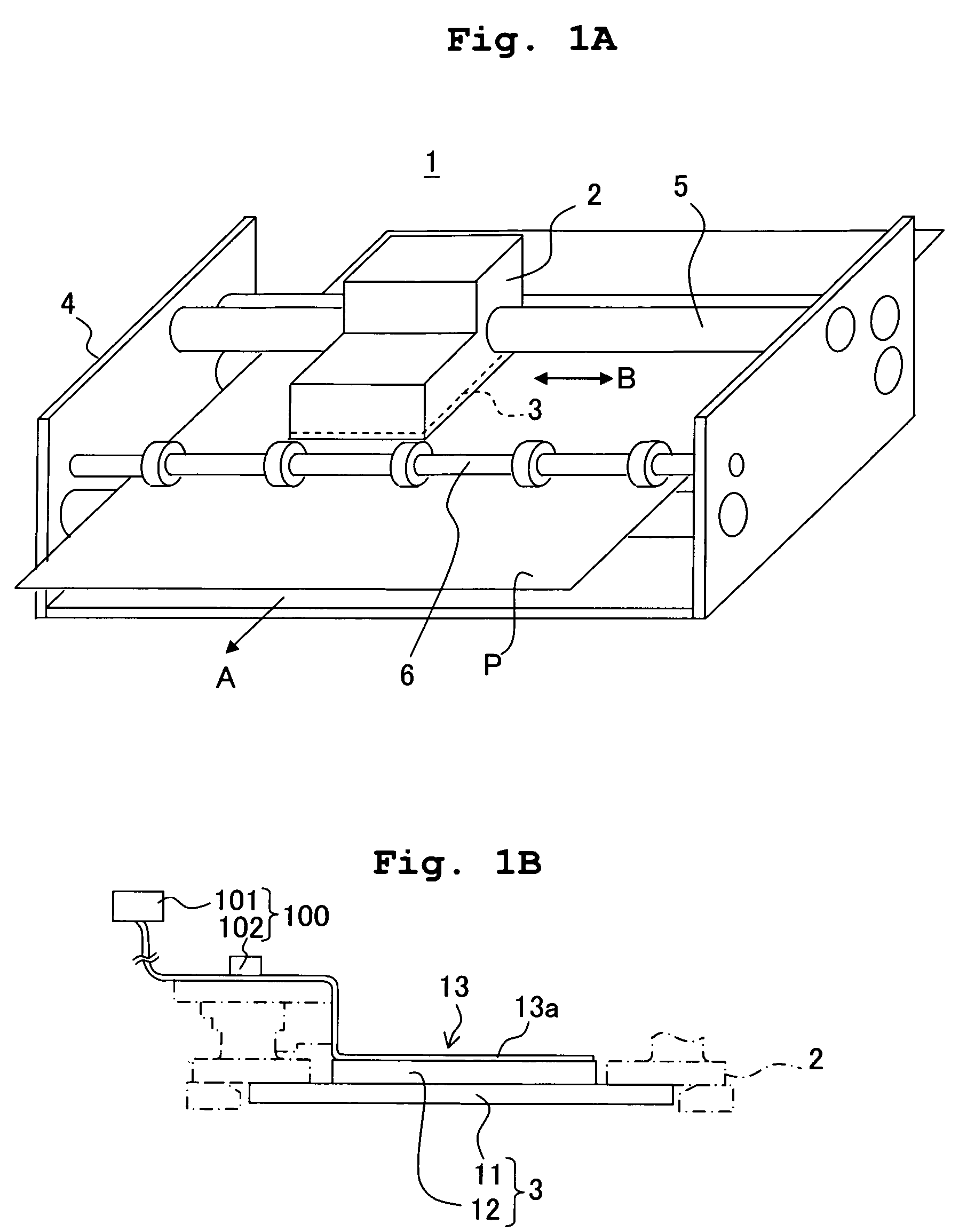
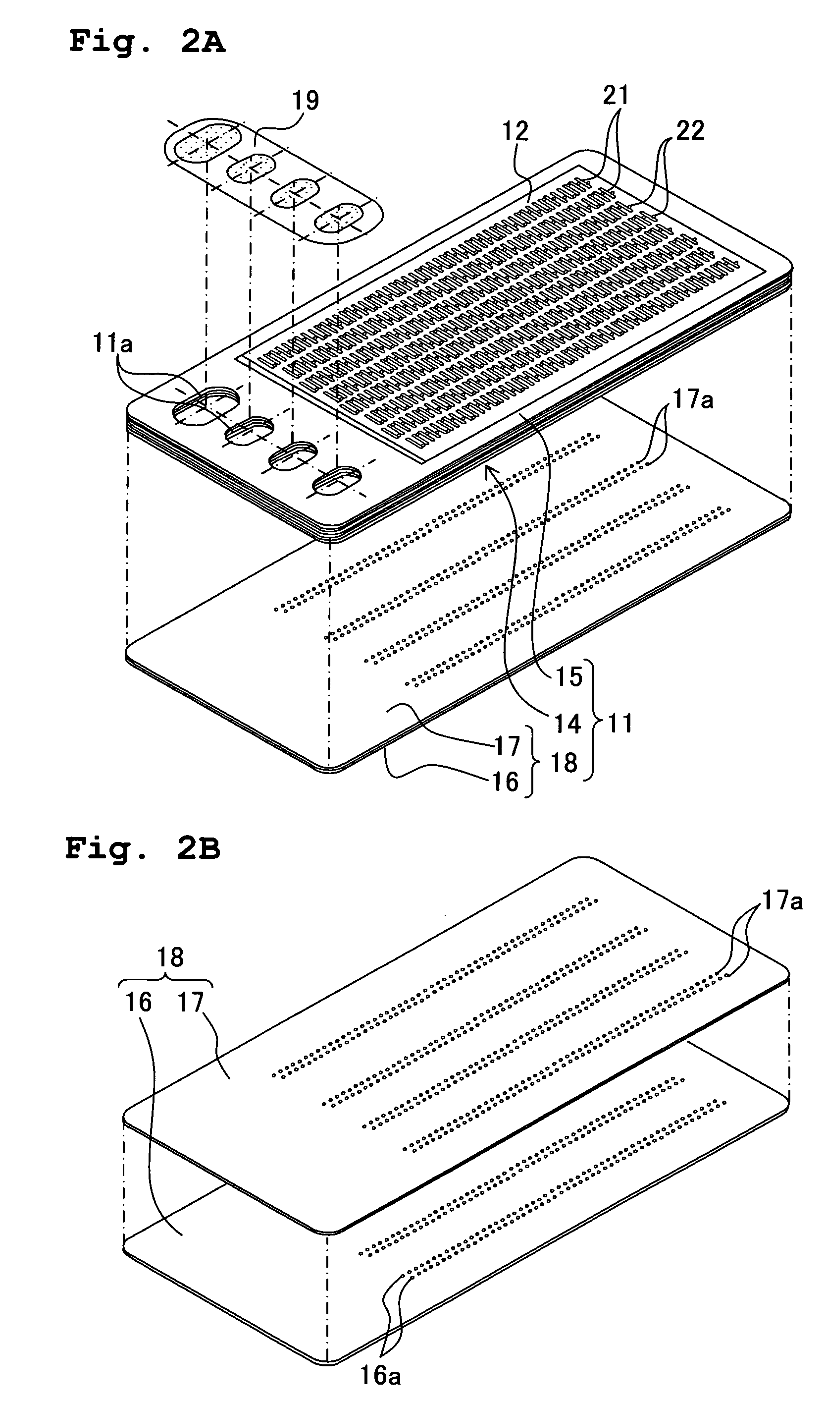
The ink-jet printer head includes a cavity unit which has a plurality of pressure chambers arranged in a plurality of pressure-chamber rows; an actuator unit which has individual surface electrodes corresponding to the pressure chambers respectively, and land portions conducted to the individual surface electrodes respectively; and a flexible cable which has connection terminals and signal lines. The land portions and the connection terminals are electrically connected. In each of the pressure-chamber rows, the land portions are arranged such that a certain land portion is shifted from another land portion adjacent to the certain land portion in a longitudinal direction of the pressure chambers. Accordingly, even when the pressure chambers are arranged highly densely, it is possible to electrically connect the flexible cable and the actuator unit easily.
Description
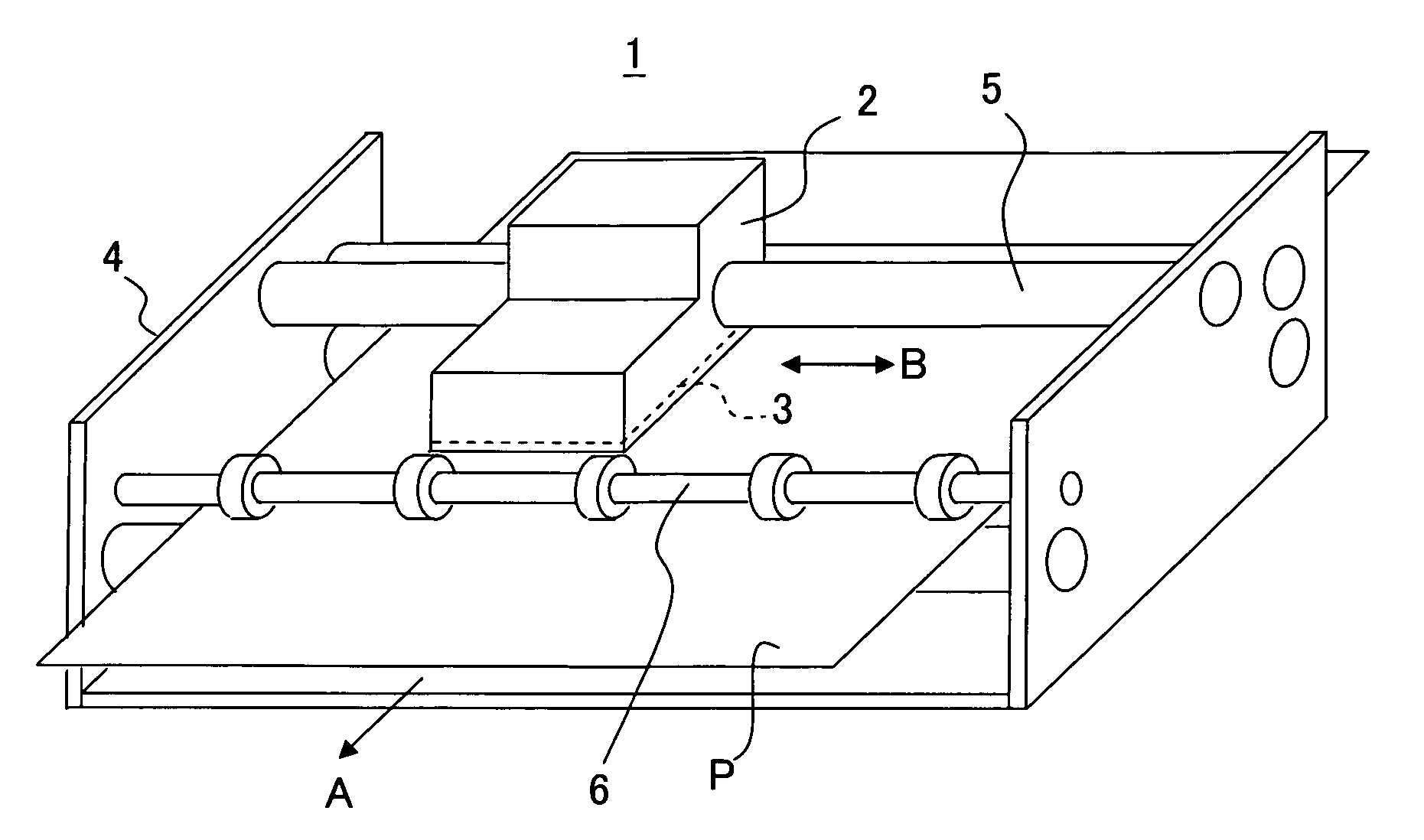
CROSS REFERENCE TO RELATED APPLICATION [0001] The present application claims priority from Japanese Patent Application No. 2005-218994, filed on Jul. 28, 2005, the disclosure of which is incorporated herein by reference in the entirety. BACKGROUND OF THE INVENTION [0002] 1. Field of the Invention [0003] The present invention relates to an ink-jet printer, a head for the ink-jet printer, and a flexible cableusable for the ink-jet printer head. [0004] 2. Description of the Related Art [0005] As an ink-jet printer which performs recording on a recording medium by discharging an ink, there is an ink-jet printer which is hitherto widely known and which is provided with a cavity unit which has a plurality of nozzles, a plurality of pressure chambers communicating with the nozzles respectively, and a manifold temporarily storing an ink to be supplied to the pressure chambers; and an actuator unit which has a plurality of individual electrodes formed corresponding to the pressure chambers,...
Claims
Application Information
Patent Timeline
Application Date:The date an application was filed.
Publication Date:The date a patent or application was officially published.
First Publication Date:The earliest publication date of a patent with the same application number.
Issue Date:Publication date of the patent grant document.
PCT Entry Date:The Entry date of PCT National Phase.
Estimated Expiry Date:The statutory expiry date of a patent right according to the Patent Law, and it is the longest term of protection that the patent right can achieve without the termination of the patent right due to other reasons(Term extension factor has been taken into account ).
Invalid Date:Actual expiry date is based on effective date or publication date of legal transaction data of invalid patent.

