Method and apparatus for enhancing flash and ambient images

Inactive Publication Date: 2007-02-01
MITSUBISHI ELECTRIC RES LAB INC
View PDF4 Cites 64 Cited by
  • Summary
  • Abstract
  • Description
  • Claims
  • Application Information

AI Technical Summary

Benefits of technology

[0017] The well-lit images can be analyzed, and are adaptively sampled to minimize the number of images needed to be acquired for a scene. Methods that enhance the quality of images are also provided.
[0018] The ratio of brightne

Problems solved by technology

Flash images are known t

Method used


Image

  • Method and apparatus for enhancing flash and ambient images
  • Method and apparatus for enhancing flash and ambient images
  • Method and apparatus for enhancing flash and ambient images

Examples


Embodiment Construction

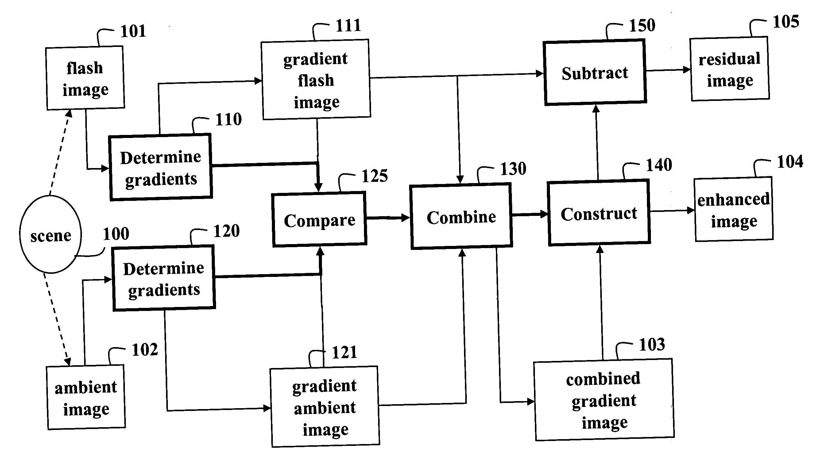
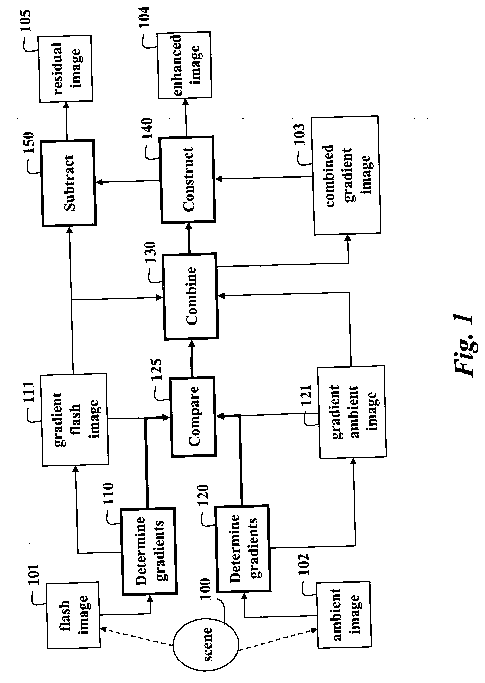
[0034]FIG. 1 shows a method and system for enhancing images according to one embodiment of the invention. A flash image 101 is acquired of a scene 100 by a camera. In this case, the scene is illuminated with a first lighting condition, e.g., a flash unit. Gradient flash images 111 are determined 110 from the flash image. An ambient image 102 is acquired of the scene by the camera. In this case, the scene is illuminated by a second lighting condition, e.g., the ambient light. Gradient ambient images 121 are determined 120 for the ambient image.

[0035] In the case that the scene is also illuminated by ambient light while acquiring the flash image, the relative amount of ambient light is relatively small. Therefore, the contribution due to ambient light can either be ignored, or a ‘pure’ flash image can be obtained by subtracting the ambient image from the flash image when some ambient light is present in the scene.

[0036] The first and second example lighting conditions for the embodi...


PUM


Abstract

A method and system generate an enhanced output image. A first image is acquired of a scene illuminated by a first illumination condition. A second image is acquired of the scene illuminated by a second illumination condition. First and second gradient images are determined from the first and second images. Orientations of gradients in the first and second gradient images are compared to produce a combined gradient image, and an enhanced output image is constructed from the combined gradient image.

Description

FIELD OF THE INVENTION [0001] The invention relates generally to computer graphics, and more particularly to enhancing images acquired of a scene with ambient and flash unit illumination. BACKGROUND OF THE INVENTION [0002] Flash units are often used to acquire an image of a scene under low-light conditions. However, flash units produce a variety of undesirable effects and artifacts. Objects near the flash unit tend to be over-exposed, while distant objects tend to be under-exposed because the flash intensity decreases as the square of the distance from the camera. [0003] Furthermore, flash units also produce undesirable reflections. Often, one sees the reflection of an object that lies outside the field of view of the camera but is strongly lit by the flash unit, or by a specular object within the field of view. Even more often, one sees strong highlights due to reflections by glossy objects in the scene. [0004] Images acquired of shallow-depth, indoor scenes with flash units can ha...

Claims


Application Information

Patent Timeline
IPC IPC(8): H04N5/222
CPCH04N5/2355H04N5/2352H04N23/72H04N23/741
Inventor RASKAR, RAMESHAGRAWAL, AMIT
Owner MITSUBISHI ELECTRIC RES LAB INC
Why Eureka
Try Eureka