Cartridge case and disc cartridge

a cartridge case and disc cartridge technology, applied in the field of cartridge cases and disc cartridges, can solve the problems of difficult to smoothly load the disc cartridge, difficult to correctly position the disc cartridge b>, and the risk of the outer shell, and achieve the effects of smooth loading into the recording/reproducing apparatus, and reliably loading to

Inactive Publication Date: 2007-02-01
TDK CORPARATION
View PDF6 Cites 3 Cited by
  • Summary
  • Abstract
  • Description
  • Claims
  • Application Information

AI Technical Summary

Benefits of technology

[0011] With the above cartridge case, by constructing the first shell so that cylindrical convex portions, in each of which a positioning reference hole is formed, are erected on an inner surface of a main plate of the first shell, and constructing the second shell so that insertion holes that allow positioning pins to be inserted into the positioning reference holes are formed in a main plate of the second shell, even if the second shell is placed on and attached to the first shell in a state where the second shell is slightly displaced relative to the first shell, the positioning reference holes into which the positioning pins are inserted will not be displaced and therefore the cartridge case can be correctly positioned relative to a recording / reproducing apparatus or the like without being affected by the attachment position of the second shell on the first shell. Accordingly, with a disc cartridge constructed by enclosing a disc-shaped information medium inside this cartridge case, it is possible to carry out disc access properly for the information medium inside the cartridge case that has been correctly positioned inside the recording / reproducing apparatus.
[0012] Also, the second shell may include two shell main bodies in each of which at least one of the insertion holes is formed, the shell main bodies may be capable of being separately attached to the first shell, and two cylindrical convex portions may be erected on the first shell at positions into which the positioning pins are capable of being inserted via the insertion holes. With this construction, even if there are slight fluctuations in the relative positional relationship of the shell main bodies attached to the first shell between individual products, it will still be possible to avoid a state where the positioning reference holes on the cartridge case are displaced. Accordingly, it is possible to correctly position the cartridge case with respect to a recording / reproducing apparatus or the like.
[0013] The cylindrical convex portions may be formed with outer diameters of the cylindrical convex portions set equal to inner diameters of the insertion holes. With this construction, when the second shell has been placed on (i.e., fitted onto) the first shell, the rim portions of the insertion holes touch (i.e., are in contact with) the circumferential surfaces of the cylindrical convex portions, thereby making it possible to avoid a situation where the second shell is fitted onto the first shell in a greatly displaced state. This means that it is possible to avoid a state where the maximum width and maximum length of the cartridge case exceed standard ranges due to the second shell being displaced with respect to the first shell. As a result, the cartridge case can be smoothly loaded into the recording / reproducing apparatus and can be reliably loaded to the recording / reproducing position.
[0014] Also, the cylindrical convex portions may be formed so that in a state where the first shell and the second shell have been placed on one another, front end surfaces of the cylindrical convex portions become flush with an outer surface of the main plate of the second shell. With this construction, it is possible to avoid a situation where base ends of the positioning pins contact the surface of the main plate of the first shell (i.e., the rim portions of the insertion holes), which would make it difficult to insert the front ends of the positioning pins as far as standard positions inside the positioning reference holes and also to avoid a situation where the cylindrical convex portions protrude from the main plate of the first shell and catch on various components and the like inside the recording / reproducing apparatus.
[0015] Another cartridge case according to the present invention is constructed so as to be capable of enclosing an information medium inside a cartridge main body that includes a first shell and a second shell and is formed by placing the first shell and the second shell on one another, wherein the second shell is constructed so as not to protrude from the first shell in at least a width direction of the cartridge main body when the second shell has been placed on the first shell. Note that the expression “width direction” in the present specification refers to a direction perpendicular to the direction in which the cartridge case is loaded into a recording / reproducing apparatus or the like. With this construction, even if the second shell is attached to (placed on) the first shell in a slightly displaced state, the second shell will not greatly jut out (or protrude out) from the first shell, and therefore a situation where the maximum width of the cartridge case exceeds the width of the first shell can be avoided. Accordingly, the cartridge case can be smoothly loaded into the recording / reproducing apparatus and can be reliably loaded to the recording / reproducing position.
[0016] With the other cartridge case, the second shell may include two shell main bodies that are capable of being attached to the first shell so that the shell main bodies are apart in a width direction of the first shell to form a disc access opening between the shell main bodies, and the shell main bodies may be formed so that a total of a standard width of the disc access opening along the width direction of the first shell, a length along the width direction of one of the shell main bodies, and a length along the width direction of another of the shell main bodies is shorter than a width of the first shell. According to this construction, even if both shell main bodies are attached to (placed on) the first shell in a slightly displaced state, both shell main bodies will not greatly jut out (or protrude out) from the first shell, and therefore a situation where the maximum width of the cartridge case exceeds the width of the first shell can be avoided. Accordingly, the cartridge case can be smoothly loaded into the recording / reproducing apparatus and can be reliably loaded to the recording / reproducing position.

Problems solved by technology

In this way, with the conventional disc cartridge 1x, there is the problem that since the lower shells 7x and 8x are displaced with respect to the upper shell 6x, it becomes difficult to correctly position the disc cartridge 1x with respect to the recording / reproducing apparatus.
This means that when the disc cartridge 1x is loaded into the recording / reproducing apparatus, there is the risk of the outer shell 2x (i.e., the lower shells 7x and 8x) contacting the disc holder and the like and making it difficult to smoothly load the disc cartridge 1x.
This means that there is the risk of it becoming difficult to reliably load the disc cartridge 1x to a recording / reproducing position inside the recording / reproducing apparatus.

Method used


Image

  • Cartridge case and disc cartridge
  • Cartridge case and disc cartridge
  • Cartridge case and disc cartridge

Examples


Embodiment Construction

[0030] Preferred embodiments of a cartridge case and a disc cartridge according to the present invention will now be described with reference to the attached drawings.

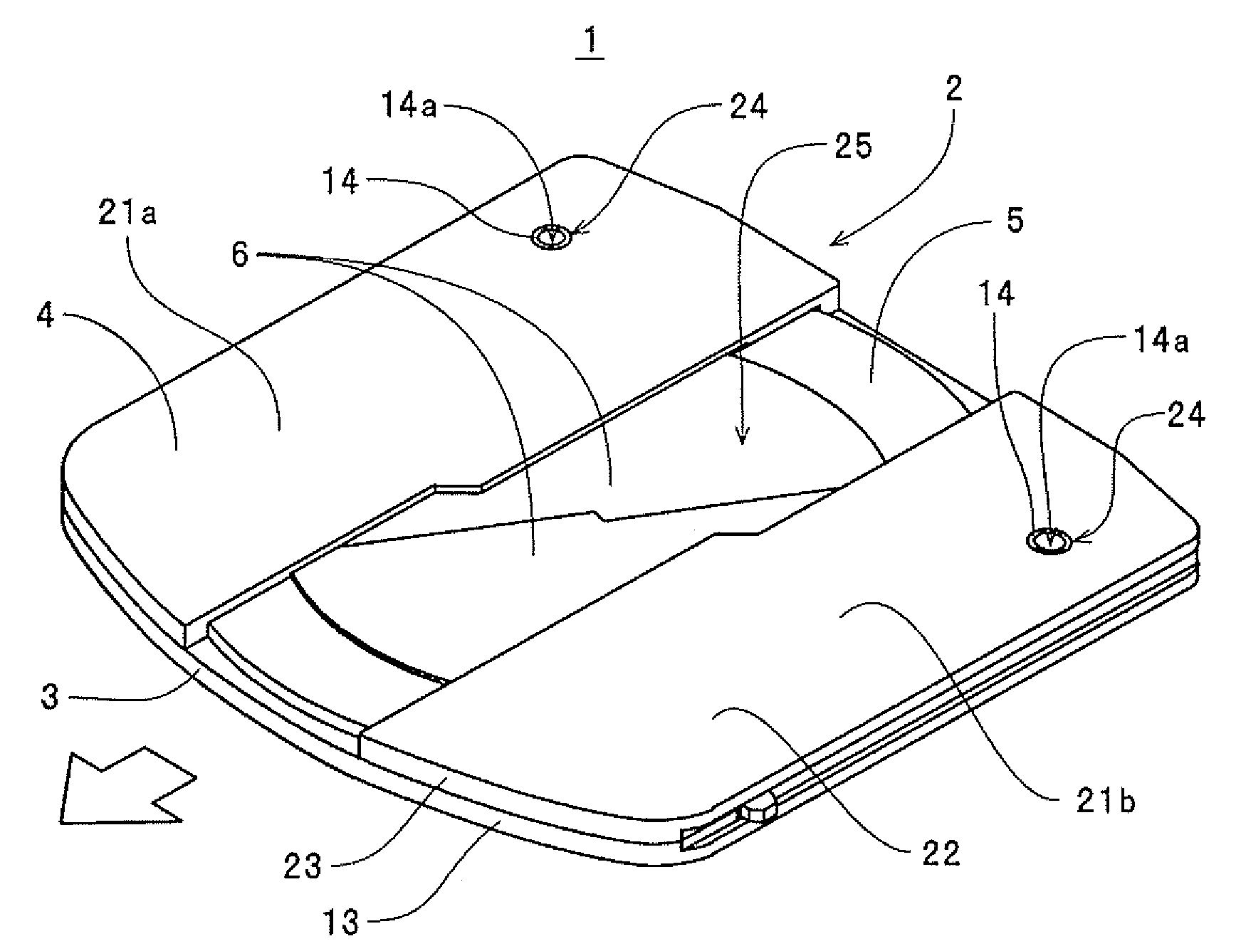
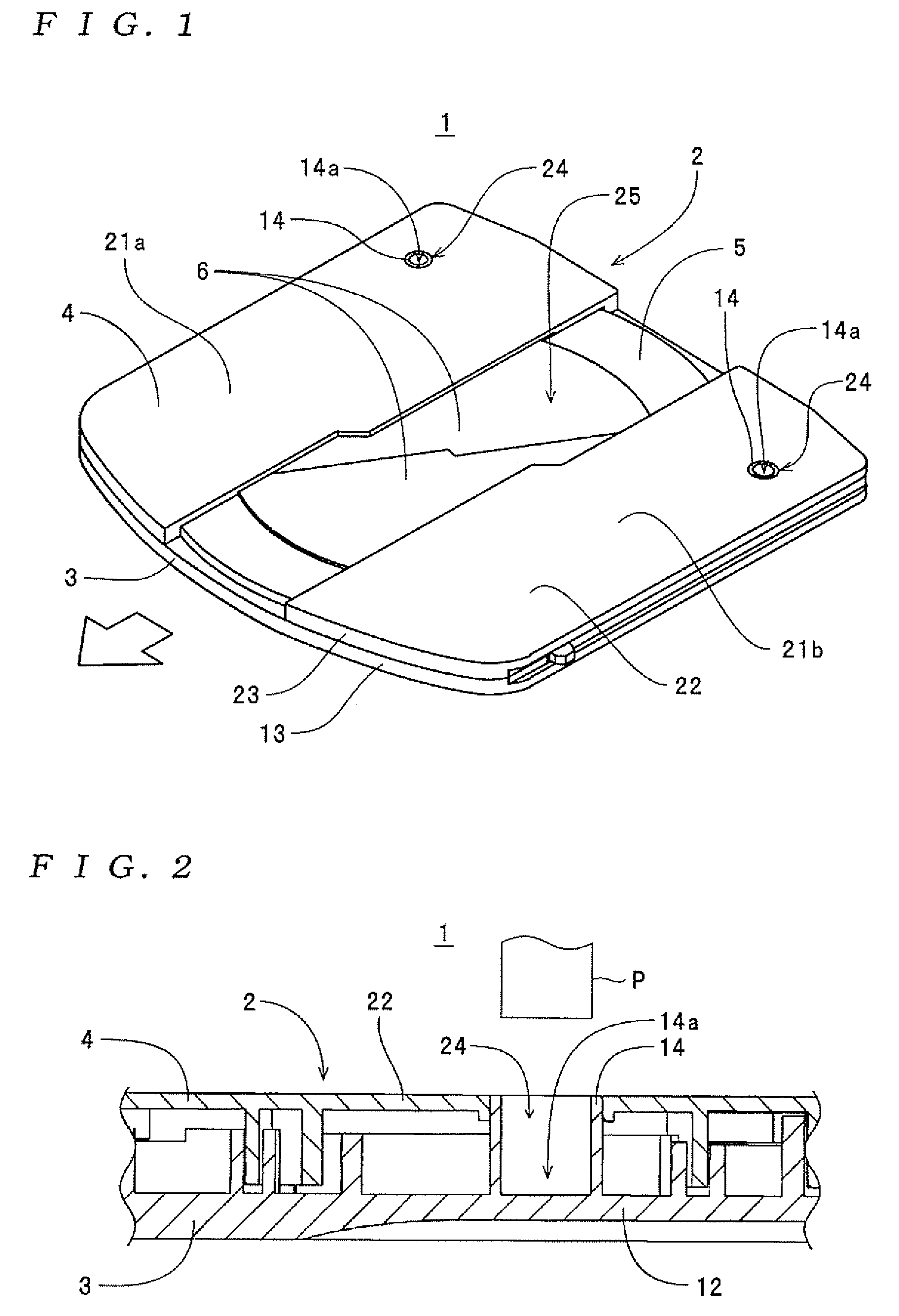
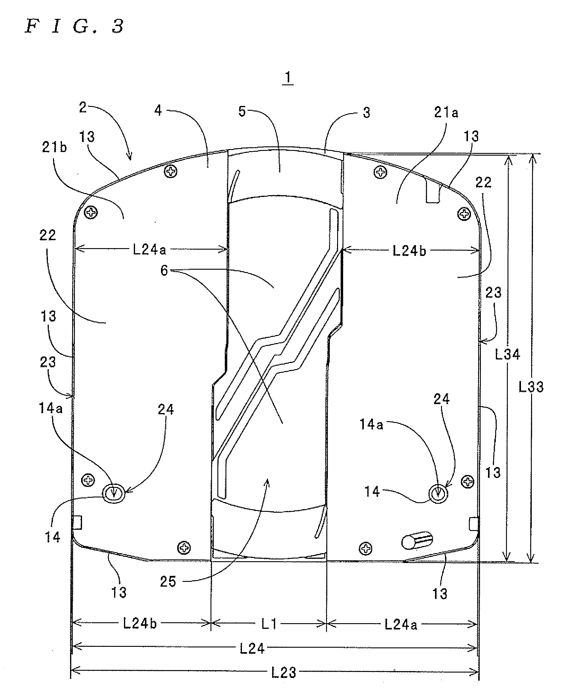
[0031] A disc cartridge 1 shown in FIGS. 7 to 3 is a cartridge-type information medium constructed so as to be capable of recording and reproducing various types of data, and is constructed so that a disc tray 5, a shutter member 6, and the like are enclosed together with an optical disc (one example of a “disc-shaped information medium” for the present invention: not shown) inside a cartridge case 2. The cartridge case 2 includes an upper shell 3 and a lower shell 4 formed so as to be capable of fitting together (i.e., capable of being placed on top of one another). Note that with the cartridge case 2, a “cartridge main body” for the present invention is constructed of a combination of the upper shell 3 and the lower shell 4.

[0032] The upper shell 3 corresponds to a “first shell” for the present invention and as sho...


PUM

PropertyMeasurementUnit
outer diametersaaaaaaaaaa
inner diametersaaaaaaaaaa
widthaaaaaaaaaa

Abstract

A cartridge case is constructed so as to be capable of enclosing an information medium inside a cartridge main body that includes a first shell and a second shell and is formed by placing the first shell and the second shell on one another. Cylindrical convex portions, each of which has a positioning reference hole formed in a central portion thereof, are erected on an inner surface of a main plate of the first shell. Insertion holes that allow positioning pins to be inserted into the positioning reference holes of the cylindrical convex portions are formed in a main plate of the second shell.

Description

BACKGROUND OF THE INVENTION [0001] 1. Field of the Invention [0002] The present invention relates to a cartridge case constructed of a first shell and a second shell so as to be capable of enclosing an information medium and to a disc cartridge constructed by enclosing a disc-shaped information medium inside the cartridge case. [0003] 2. Description of the Related Art [0004] As one example of a disc cartridge equipped with this type of cartridge case, Japanese Laid-Open Patent Publication No. 2004-318930 discloses a disc cartridge constructed so that an inner shell, a shutter member, and a disc-shaped recording medium are enclosed inside an outer shell (i.e., a cartridge case). With this disc cartridge, the outer shell is constructed by a first shell (hereinafter also referred to as an “upper shell”) and a pair of second shells (hereinafter also referred to as “lower shells”), and by screwing both lower shells to the upper shell, a box-shaped case in which a disc-shaped recording me...

Claims


Application Information

Patent Timeline
Patent Type & Authority Applications(United States)
IPC IPC(8): G11B23/03
CPCG11B23/0316G11B23/0308
Inventor KANEDA, HIROSHIIKEBE, MASARUHASHIZUME, KENJI
Owner TDK CORPARATION
Why Eureka
Try Eureka