Data transmission method, data reception method, data transport method, data transmission apparatus, data reception apparatus and data transport system as well as communication terminal

a data transmission and data technology, applied in multi-frequency code systems, multiplex communication, orthogonal multiplexes, etc., can solve the problems of large amount of transmitting power as a whole, noise characteristics become deteriorated, and the transmission rate is raised, the transmission rate is reduced, and the transmission efficiency is improved.

Inactive Publication Date: 2007-02-01
SATO MASANORI
View PDF16 Cites 9 Cited by
  • Summary
  • Abstract
  • Description
  • Claims
  • Application Information

AI Technical Summary

Benefits of technology

[0017] With the above configuration, only the first data row is transmitted as the data which is transmitted on a transmission path, and the second data row can be obtained on the receiving side based on the selection of the orthogonal code which has diffused the first data row. Therefore, the first and second data rows can be obtained on the receiving side only by performing processing of transmitting the first data row; the transmission power becomes unnecessary with respect to the second data row; and a transmission rate can be raised with less transmission power, so that efficient transmission can be performed. Particularly, when being included as a transmission apparatus driven by a battery, this configuration is efficient to make sustaining time of the battery longer since there is no need to raise the transmitting power. Moreover, there is no need to make the modulation method or the like multi-valued though the transmission rate can be increased, so that it is possible to relax a restriction (or to be made equal to a restriction of a conventional low transmission rate) on an analog portion.

Problems solved by technology

However, when wireless transmission is performed in the manner shown in FIGS. 12 and 13, there is a problem in which transmitting power is required as much as the number of orthogonal codes to be used.
In other words, when two orthogonal codes are used, twice as much transmitting power is required, and when four orthogonal codes are used, the transmitting power four times as much is required, and therefore, there has been a problem in which a great amount of transmitting power is necessary as a whole in proportion to the number of orthogonal codes to be used.
However, when the cycle of the orthogonal code is shortened, noise characteristics become deteriorated to that extent, and therefore, it becomes necessary to increase the transmitting power, after all.
Further, although it is also considered to raise the transmission rate by employing a modulation method of using multiple values, the noise characteristics also deteriorate in this case and therefore, the transmitting power needs to increase after all.
However, since a distance between signals becomes short when switching over to the multi-value modulation, the noise characteristics become deteriorated and the transmitting power needs to increase in order to secure a communication quality.
Particularly, in case of a communication terminal such as a mobile phone unit which is operated using a battery, such large increase in transmission power is not desirable due to the reason that sustaining time of the battery of the terminal may be shortened.

Method used


Image

  • Data transmission method, data reception method, data transport method, data transmission apparatus, data reception apparatus and data transport system as well as communication terminal
  • Data transmission method, data reception method, data transport method, data transmission apparatus, data reception apparatus and data transport system as well as communication terminal
  • Data transmission method, data reception method, data transport method, data transmission apparatus, data reception apparatus and data transport system as well as communication terminal

Examples


Embodiment Construction

[0031] Hereinafter, embodiments of the present invention are explained referring to FIGS. 1 through 10.

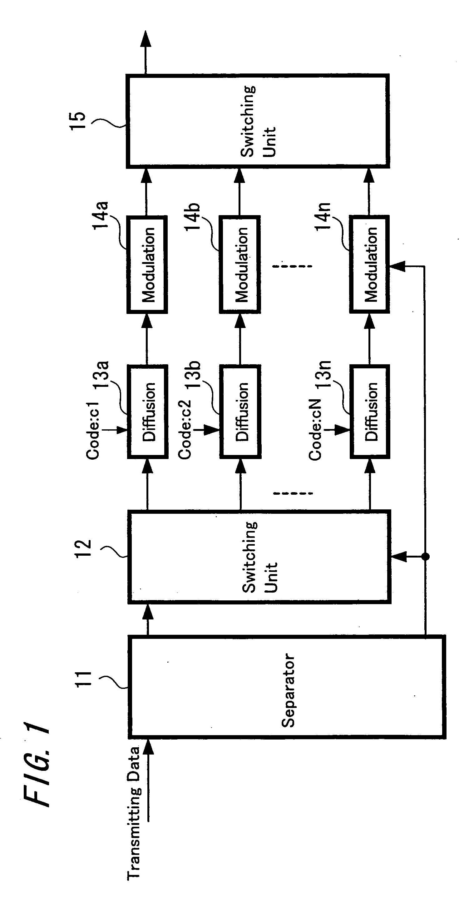
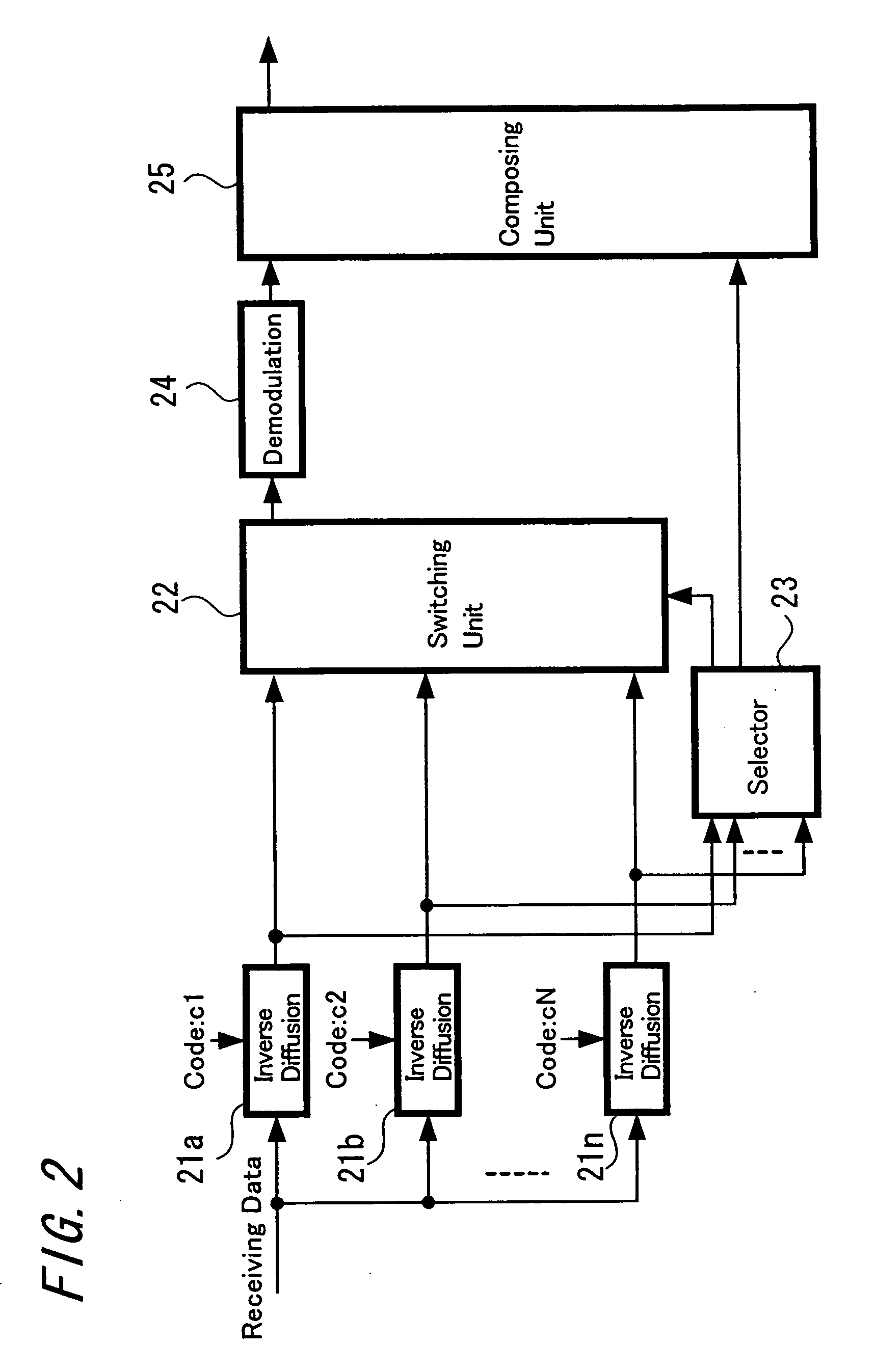
[0032] First, a principle of transmission according to an embodiment of the present invention is explained referring to FIGS. 1 and 2. FIG. 1 is a diagram showing the principle and configuration on a transmitting side, and FIG. 2 is a diagram showing the principle and configuration on a receiving side.

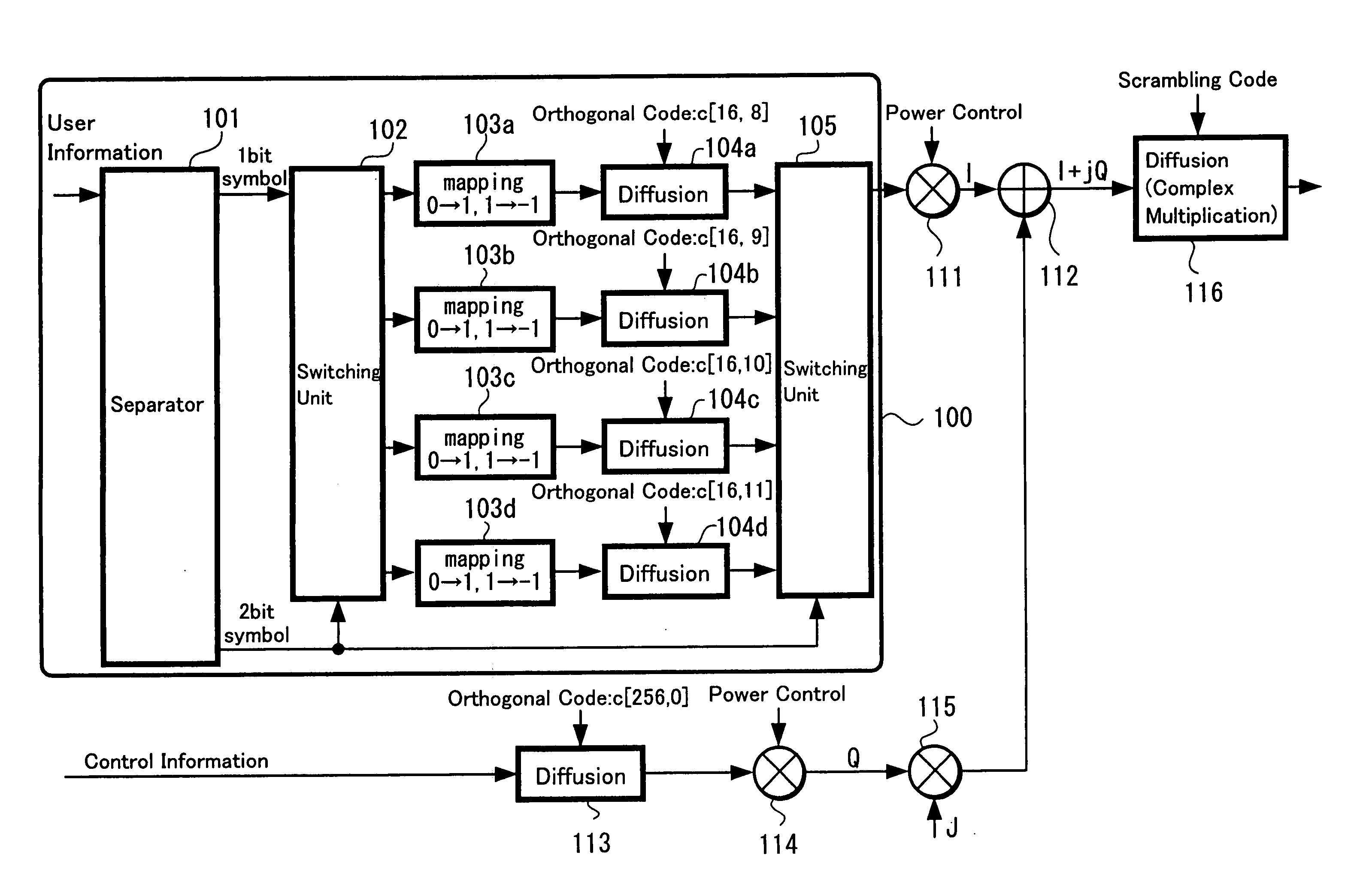
[0033] An explanation is made to the principle and configuration on the transmitting side shown in FIG. 1; transmitting data is supplied to a separator 11. The supplied transmitting data is separated into two systems in the separator 11. For example, in case of the transmitting data in which one unit (one symbol) includes four bits, it is separated into two bits each, and one two-bit data is supplied to a switching unit 12. Further, the other two-bit data is supplied to the switching units 12 and 15 as switching control information.

[0034] The one two-bit data supplied to the switch...


PUM


Abstract

On a transmitting side, input data is separated into a first data row and a second data row by the unit of predetermined symbol; one code is selected among a plurality of orthogonal codes in accordance with the separated second data row; the first data row is diffused using the selected code; and the diffused first data row is modulated to be transmitted. On a receiving side, a receiving signal is inversely diffused individually using the same plurality of orthogonal codes as the orthogonal codes on the transmitting side; a signal which is inversely diffused using a correct orthogonal code is selected among the inversely-diffused respective receiving signals; a first receiving data row is obtained from a demodulation of the selected signal; a second receiving data row corresponding to the correct orthogonal code which is selected by the selection is obtained; and receiving data is obtained by composing the first receiving data row and the second receiving data row.

Description

TECHNICAL FIELD [0001] The present invention relates to a data transmission method, a data reception method, a data transport method, a data transmission apparatus, a data reception apparatus and a data transport system as well as a communication terminal which are suitable to be applied to a wireless transmission of, for example, a CDMA (Code Division Multiple Access) method. BACKGROUND ART [0002] Hitherto, the CDMA method has been put into a practical use as the efficient wireless transmission. In the CDMA method, transmitting data is diffused using an orthogonal code and is multiplexed to be transmitted. There is a case in which control information (power control information, information for synchronous detection and the like) other than user information (audio data or packet data or the like) is contained in the transmitting data. [0003]FIG. 11 is a block diagram showing a conventional example in which wireless transmission processing is performed in the CDMA method by multiplex...

Claims


Application Information

Patent Timeline
Patent Type & Authority Applications(United States)
IPC IPC(8): H04K1/10H04B1/7075H04J13/00H04J11/00H04J13/18
CPCH04J13/18H04J13/12H04B1/7097
Inventor SATO, MASANORI
Owner SATO MASANORI
Why Eureka
Try Eureka