Coding device, coding method, decoding device, decoding method, and programs of same

Inactive Publication Date: 2007-02-01
SONY CORP +1
View PDF10 Cites 62 Cited by
  • Summary
  • Abstract
  • Description
  • Claims
  • Application Information

AI Technical Summary

Benefits of technology

[0014] According to the present invention, a coding device, a coding method, a decoding device, a decoding

Problems solved by technology

In the above coding device, however, for example, at a flat image region in the picture data, a noise pattern known as “refresh

Method used


Image

  • Coding device, coding method, decoding device, decoding method, and programs of same
  • Coding device, coding method, decoding device, decoding method, and programs of same
  • Coding device, coding method, decoding device, decoding method, and programs of same

Examples


Embodiment Construction

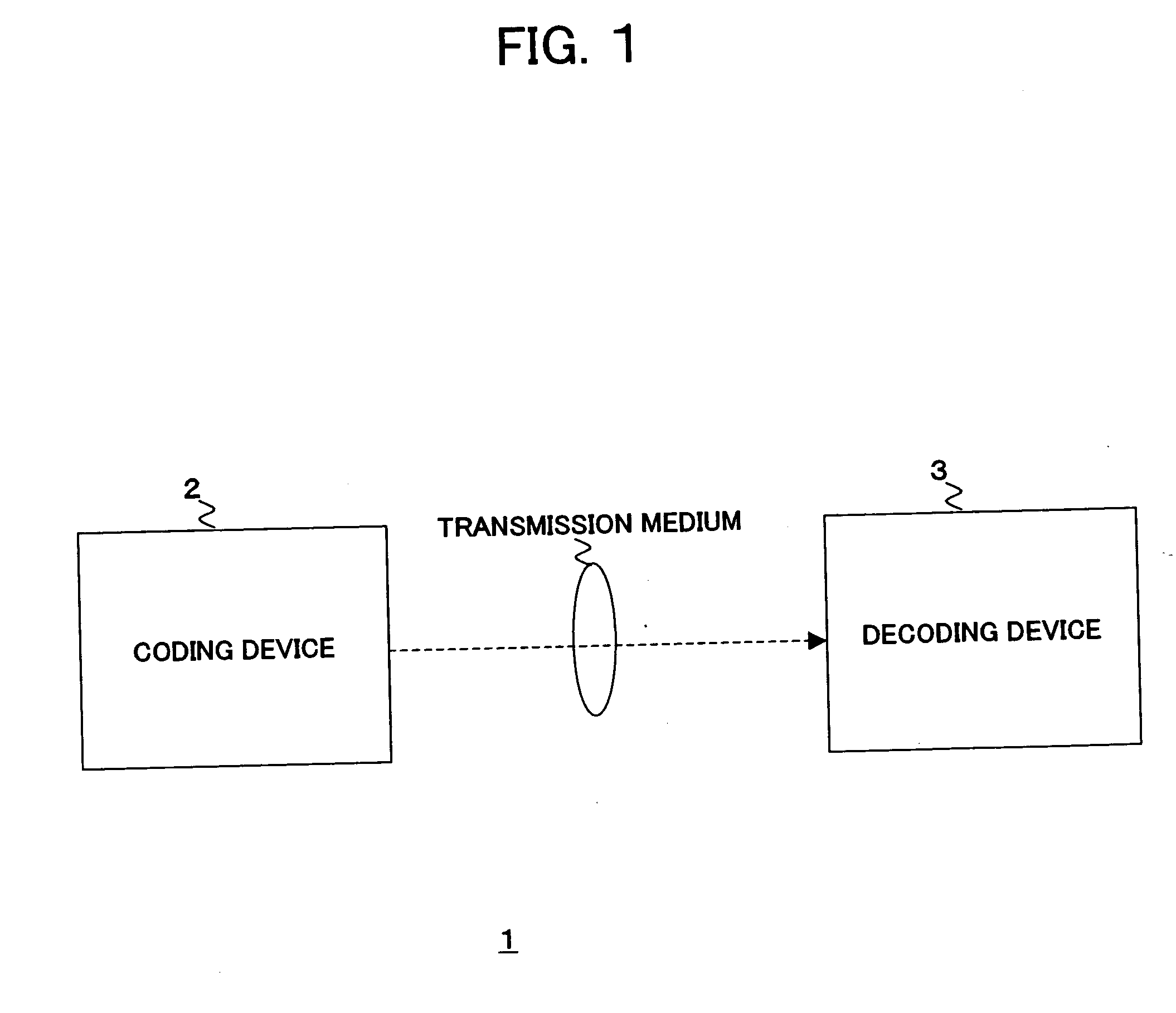
[0033] Below, an explanation will be given of a communication system 1 of a preferred embodiment of the present invention. FIG. 1 is a conceptual view of the communication system 1 of the present embodiment. As shown in FIG. 1, the communication system 1 has a coding device 2 provided on a transmission side and a decoding device 3 provided on a reception side. In the communication system 1, the coding device 2 on the transmission side generates frame image data (bit stream) compressed by a discrete cosine transform, Karhunen-Loewe transform, or other orthogonal transform and motion compensation, modulates the frame image data, then transmits the same via a satellite broadcast wave, cable TV network, telephone line network, cell phone line network, or other transmission medium. In the reception side, the decoding device 3 demodulates the received image signal, then generates and uses the frame image data decompressed by the inverse transform to the orthogonal transform at the time of...


PUM


Abstract

A coding device having a specifying unit for specifying image region data to be processed for refreshing countermeasures in image data being coded based on that image data and a refreshing countermeasure unit for applying processing for refreshing countermeasures to image region data specified by the specifying unit when coding the image data.

Description

BACKGROUND OF THE INVENTION [0001] 1. Field of the Invention [0002] The present invention relates to a coding device, a coding method, a decoding device, and a decoding method of image data and programs of the same. [0003] 2. Description of the Related Art [0004] In recent years, for the purpose of handling image data digitally and at that time transmitting and storing information highly efficiently, coding devices and decoding devices based on the MPEG (Moving Picture Experts Group), H.264 / AVC (Advanced Video Coding), and other coding systems utilizing the redundancy peculiar to image information and compressing data by a discrete cosine transform or other orthogonal transform and motion compensation are now spreading in use for both distribution of information at broadcast stations etc. and reception of the information at general homes. [0005] The above coding method assigns picture types I, P, and B based on a GOP (Group Of Pictures) structure to the plurality of picture data for...

Claims


Application Information

Patent Timeline
IPC IPC(8): G06K9/36
CPCH04N19/159H04N19/176H04N19/61H04N19/527H04N19/14H04N19/137H04N19/117H04N19/107H04N19/51
Inventor LEE, HUNG-JUMURAYAMA, JUNNAGUMO, TAKEFUMI
Owner SONY CORP
Why Eureka
Try Eureka