Gas turbine engine with purge air pump and guide

a technology of purge air and gas turbine engine, which is applied in the direction of machines/engines, liquid fuel engines, stators, etc., can solve the problems of shortened part life, difficult to achieve adequate purge air flow, and corrosion of components

Active Publication Date: 2007-02-01
RAYTHEON TECH CORP
View PDF6 Cites 25 Cited by
  • Summary
  • Abstract
  • Description
  • Claims
  • Application Information

AI Technical Summary

Benefits of technology

[0006] In a disclosed embodiment of this invention, a pump/flow guide is attached to a transition duct at a location facing a turbine rotor. The pump/flow guide moves purge air radially outwar

Problems solved by technology

One challenge in the design of gas turbine engines, is that the hot gas in the area of the turbine can begin to move radially inwardly into an inner cavity.
This would be undesirable.
Ingestion of this hot gas can lead to corrosion of the components, which can lead to shortened part life.
However, the present interface presents a tortuous flow path that makes it somewhat difficult to achieve an adequate flow of purge

Method used


Image

  • Gas turbine engine with purge air pump and guide
  • Gas turbine engine with purge air pump and guide
  • Gas turbine engine with purge air pump and guide

Examples


Embodiment Construction

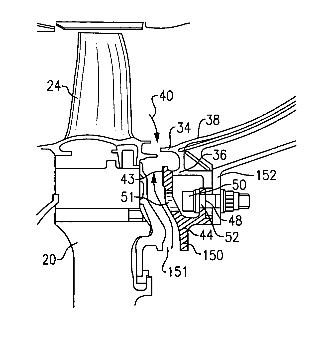
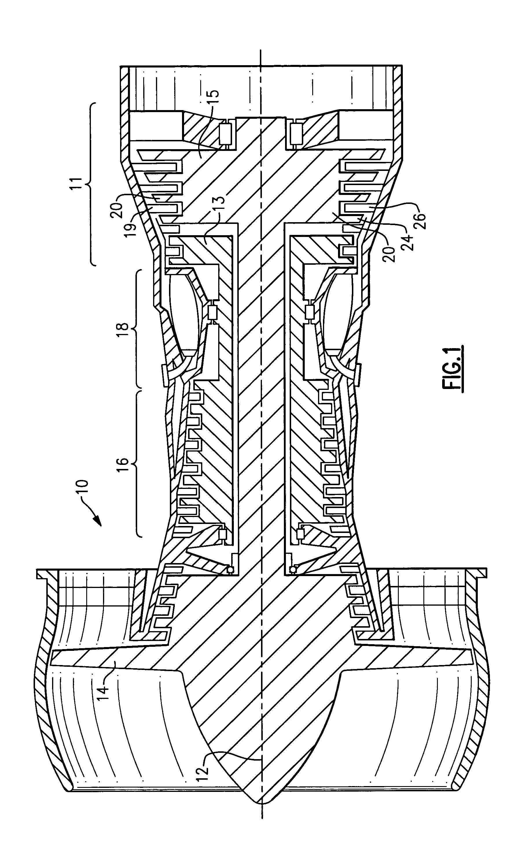
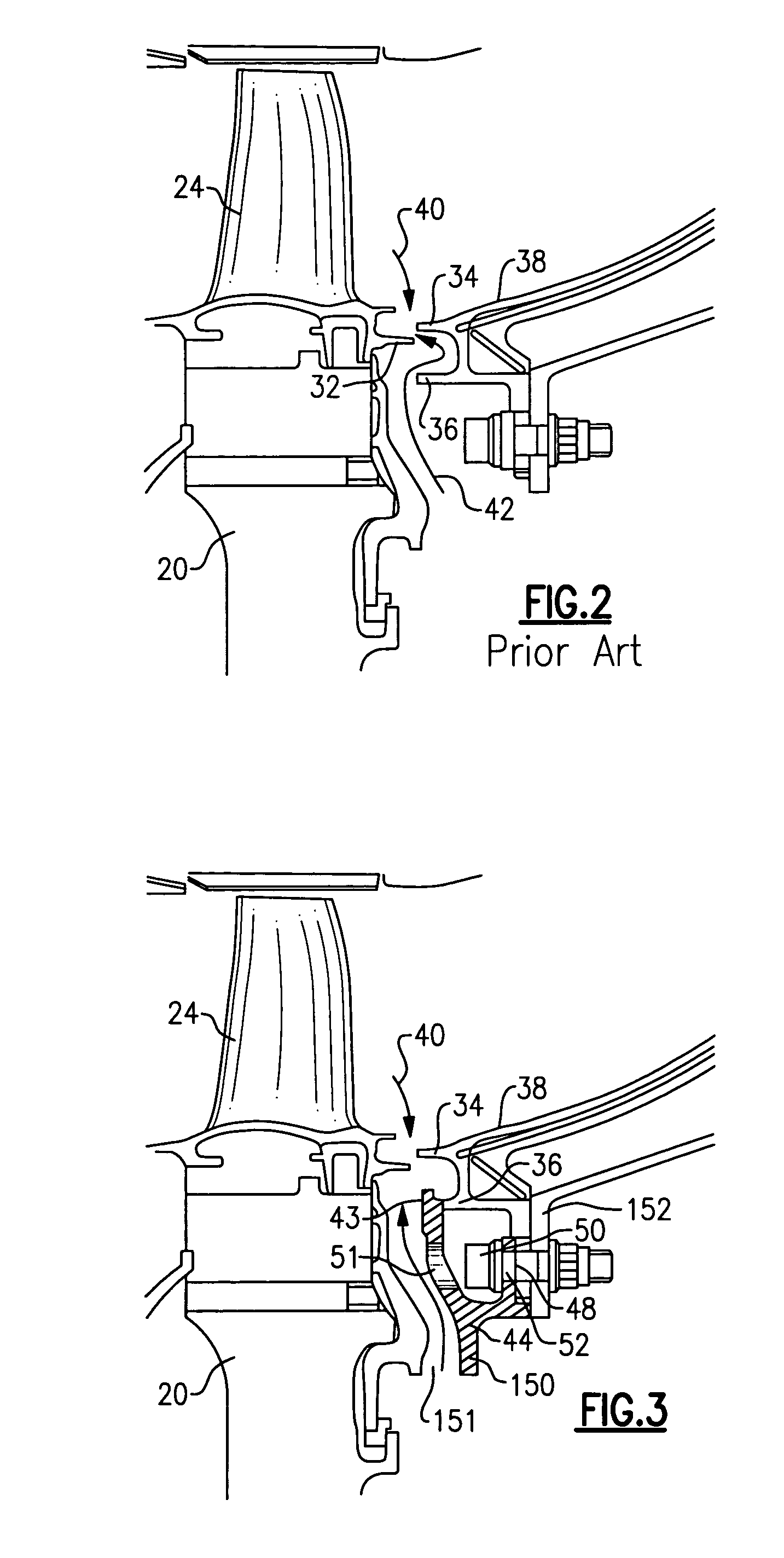
[0014] A gas turbine engine 10, such as a turbofan gas turbine engine, circumferentially disposed about an engine centerline, or axial centerline axis 12 is shown in FIG. 1. The engine 10 includes a fan 14, a compressor 16, a combustion section 18 and a turbine 20. As is well known in the art, air compressed in the compressor 16 is mixed with fuel which is burned in the combustion section 18 and expanded in turbine 20. The air compressed in the compressor and the fuel mixture expanded in the turbine 20 can both be referred to as a hot gas stream flow. The turbine 20 includes rotors 22 which rotate in response to the expansion, driving the compressor 16 and fan 14. The turbine 20 comprises alternating rows of rotary airfoils or blades 24 and static airfoils or vanes 26. This structure is shown somewhat schematically in FIG. 1.

[0015] A problem associated with the prior art gas turbine engine is illustrated in FIG. 2. As shown, a turbine blade 24 is attached to rotate with a turbine d...


PUM


Abstract

A pump/flow guide is positioned in a gas turbine engine and attached to a transition duct to face a turbine disk. The pump/flow guide provides a smooth path for guiding purge flow to resist the ingestion of hot gas. One leg of the pump/flow guide extends radially outwardly and contacts the radially inner section of the transition duct that forms a “fish mouth.” Spaced tabs on the pump/flow guide receive bolts to secure the pump/flow guide to the transition duct. The pump/flow guide thus provides a relatively smooth flow passage for purge gas flow.

Description

BACKGROUND OF THE INVENTION [0001] This application relates to a device that is added into an interface between a gas turbine rotor and a transition duct to assist and guide the flow of purge air outwardly of an inner cavity. [0002] A gas turbine engine, such as a turbo fan engine for an aircraft, includes a fan section, a compression section, a combustion section and a turbine section. An axis of the engine is centrally disposed within the engine and extends longitudinally through the sections. A primary flow path for working medium gases extends axially through the sections of the engine. A secondary flow path for working medium gases extends parallel to and radially outward of the primary flow path. [0003] The fan section includes a rotor assembly and a stator assembly. The rotor assembly of the fan includes a rotor disk and plurality of radially extending fan blades. The fan blades span across through the flow path and interact with the working medium gases and transfer energy b...

Claims


Application Information

Patent Timeline
IPC IPC(8): F01D11/00
CPCF01D5/082Y02T50/676F01D11/04F01D9/023Y02T50/60
Inventor MOORE, CHRISTOPHER W.PAOLILLO, ROGER E.CHRISIKOS, JAMES P.
Owner RAYTHEON TECH CORP
Why Eureka
Try Eureka