
Method and device for influencing combustion processes involving combustibles

a combustion process and combustion technology, applied in the direction of combustion process, combustion type, gaseous fuel burner, etc., can solve the problem of increasing energy consumption without contributing, and achieve the effect of improving the influence of combustion operations in a simple and economic way

Inactive Publication Date: 2007-02-01
BRANSTON DAVID WALTER +2
View PDF7 Cites 16 Cited by
  • Summary
  • Abstract
  • Description
  • Claims
  • Application Information

AI Technical Summary

Benefits of technology

[0016] Working on this basis, it is an object of an embodiment of the invention to provide a method and to create the associated device which improve the influencing of combustion operations with fuels in a simple and economic way. The fuels to be used are in particular, although not exclusively, gases, preferably in premixed form.
[0019] Particular advantages of an embodiment of the invention result if the system is assigned sensors and control devices which control the voltage applied to the electrodes in such a way that the combustion process is influenced in the desired way. There are advantageously sensors, one of which measures the frequency of any combustion oscillation which may be present and another of which measures the pollutant concentration in the exhaust gas. The sensors supply the input signal to a control unit which controls frequency, amplitude and phase of the voltage applied to the electrodes in such a way that the combustion oscillations and / or the pollutant concentration are minimized.

Problems solved by technology

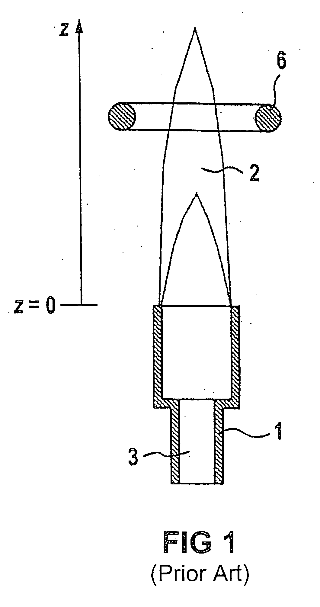
One drawback of the known art described above is that the electric field which is generated by way of the electrodes passes through a large area of the flame, while the actual effect of the electric field occurs in what is known as the flame front.
This causes an increased energy consumption without contributing to the desired effect within the flame front.

Method used


Image

  • Method and device for influencing combustion processes involving combustibles
  • Method and device for influencing combustion processes involving combustibles
  • Method and device for influencing combustion processes involving combustibles

Examples


Embodiment Construction

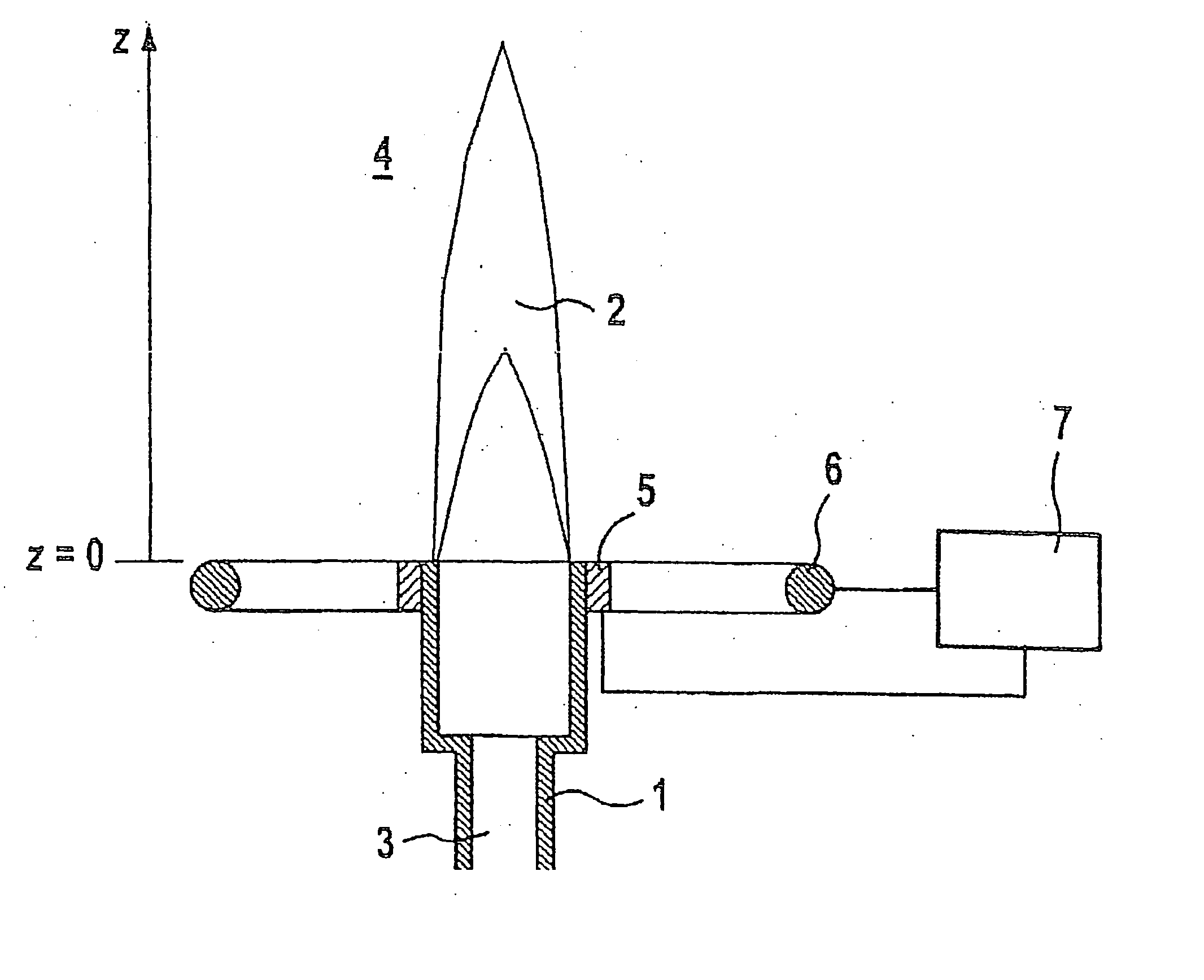
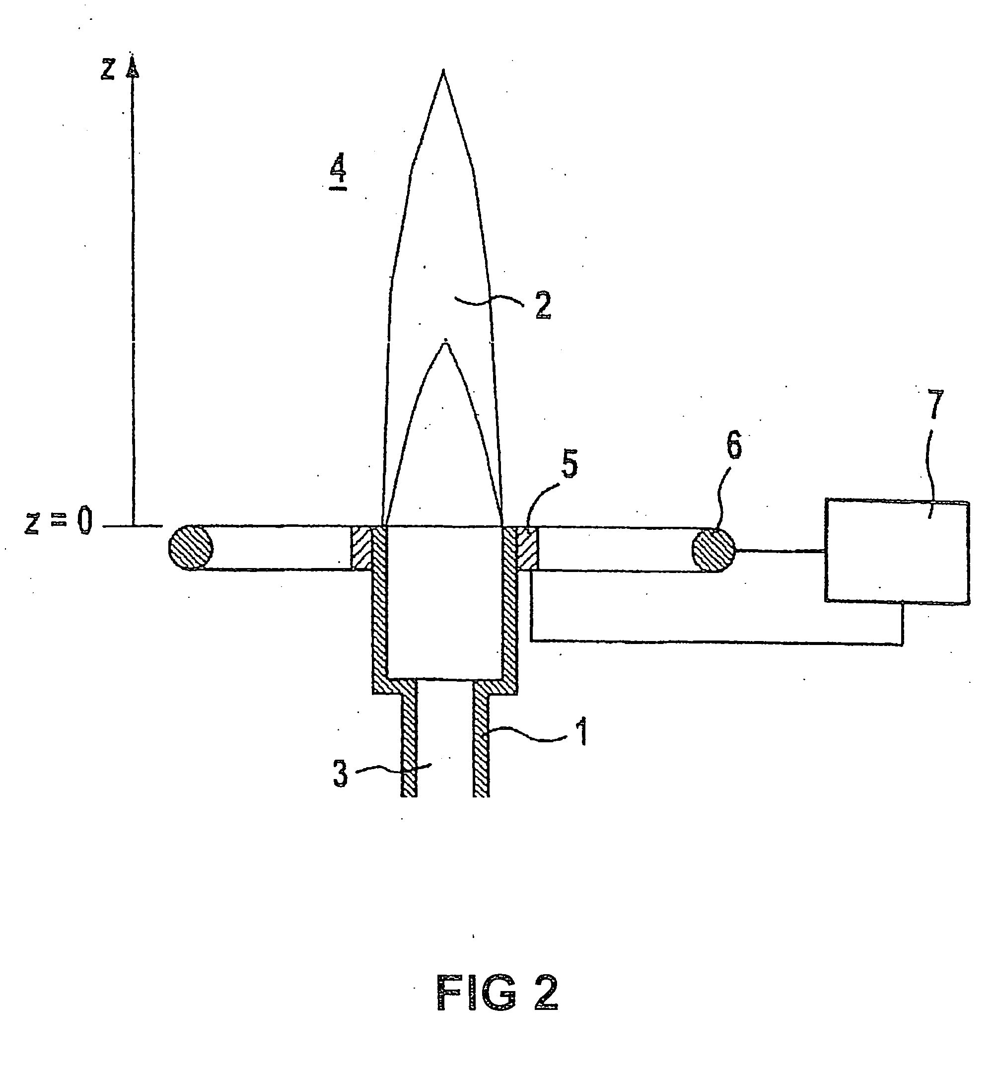
[0026] In all the examples, in each case the burner is denoted by 1 and the flame by 2. The burner I has a gas feed 3. Furthermore, the arrangement includes at least one electrode 6, which can be used to apply electric fields to the flame. The flame is scaled along the Z coordinate.

[0027]FIG. 1 has already been dealt with in the introduction, with corresponding statements relating to the known art, to which reference is made in detail.

[0028] The first exemplary embodiment of the invention, shown in FIG. 2, illustrates the flame 2 which is generated by the burner 1 for combustibles, including fuels which are in gas form, in liquid form or in the form of a solid powder transported in gas or liquids. The fuel is guided through the burner 1 into a combustion space 4 through the fuel inlet 3. The burner 1 may include electrically conductive or nonconductive material. In the former case, the burner serves as electrode, while in the latter case an electrode 5, which in this example is in...


PUM


Abstract

A method and device are for influencing combustion processes, and include an electrical device. The electrical device engages with the flame front so that the electrical field thus produced, only penetrates areas of the flame front in which a stabilizing and harmful-substance-reducing effect is produced. The electrodes of the burner are arranged outside the region of the flame in the associated device.

Description

[0001] This application is a continuation of and claims the benefit of priority under 35 U.S.C. §120 from U.S. application Ser. No. 10 / 485,401 filed Jan. 30, 2004, which is the national phase under 35 U.S.C. §371 of PCT International Application No. PCT / DE02 / 02815 having an International filing date of Jul. 31, 2002. PCT International Application No. PCT / DE02 / 02815 designates the United States of America and claims the benefit of priority under 35 U.S.C. §119 from German Patent Application number DE 101 37 683.9 filed Aug. 1, 2001. The entire contents of U.S. application Ser. No. 10 / 485,401, PCT International Application No. PCT / DE02 / 02815 and German Patent Application number DE 101 37 683.9 are hereby incorporated herein by reference.FIELD OF THE INVENTION [0002] The invention generally relates to a method for influencing combustion operations or processes involving combustibles, including fuels. Preferably, it relates to a method in which electrical devices are used to guide and / o...

Claims


Application Information

Patent Timeline
Patent Type & Authority Applications(United States)
IPC IPC(8): F23D14/46F23C99/00F23D14/02F23D14/74F23N5/16
CPCF23C99/001F23D14/02F23N5/16F23D2210/00F23D14/74
Inventor BRANSTON, DAVID WALTERLINS, GUNTERVERLEGER, JOBST
Owner BRANSTON DAVID WALTER
Learn More