Supercharge Your Innovation With Domain-Expert AI Agents!

Control apparatus for vehicular automatic transmission

a technology of automatic transmission and control apparatus, which is applied in the direction of gearing control, gearing elements, gearing, etc., can solve the problems of driving discomfort, and achieve the effect of preventing a shi

Active Publication Date: 2007-02-01
TOYOTA JIDOSHA KK
View PDF6 Cites 4 Cited by
  • Summary
  • Abstract
  • Description
  • Claims
  • Application Information

AI Technical Summary

Benefits of technology

The invention provides a hydraulic control apparatus for a vehicular automatic transmission that prevents a shift that may impair driveability when there is a failure that may cause tie-up. The apparatus includes a plurality of solenoid valves and a switching valve device. The solenoid valves are controlled to engage and disengage hydraulic frictional engagement devices. The switching valve device includes a single spool and is controlled by an electromagnetic valve to move the spool from a non-failure position to a failure position. This prevents a shift that may impair driveability in the event of a failure. The apparatus can be used in various automatic transmissions and is effective in preventing failures that may cause tie-up.

Problems solved by technology

This may make the driver feel uncomfortable.

Method used


Image

  • Control apparatus for vehicular automatic transmission
  • Control apparatus for vehicular automatic transmission
  • Control apparatus for vehicular automatic transmission

Examples


Embodiment Construction

[0034] In the following description and the accompanying drawings, the present invention will be described in more detail with reference to example embodiments.

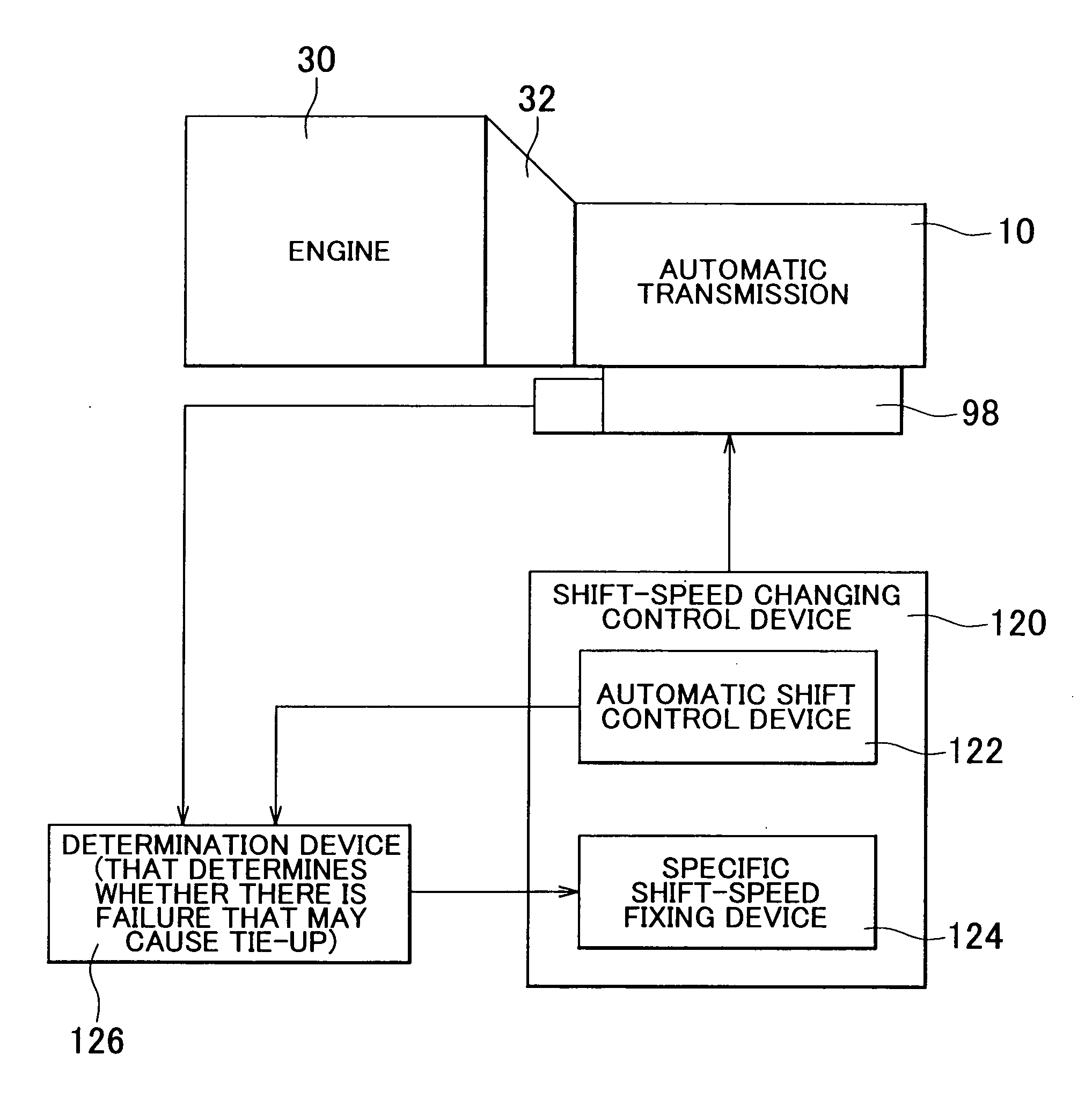
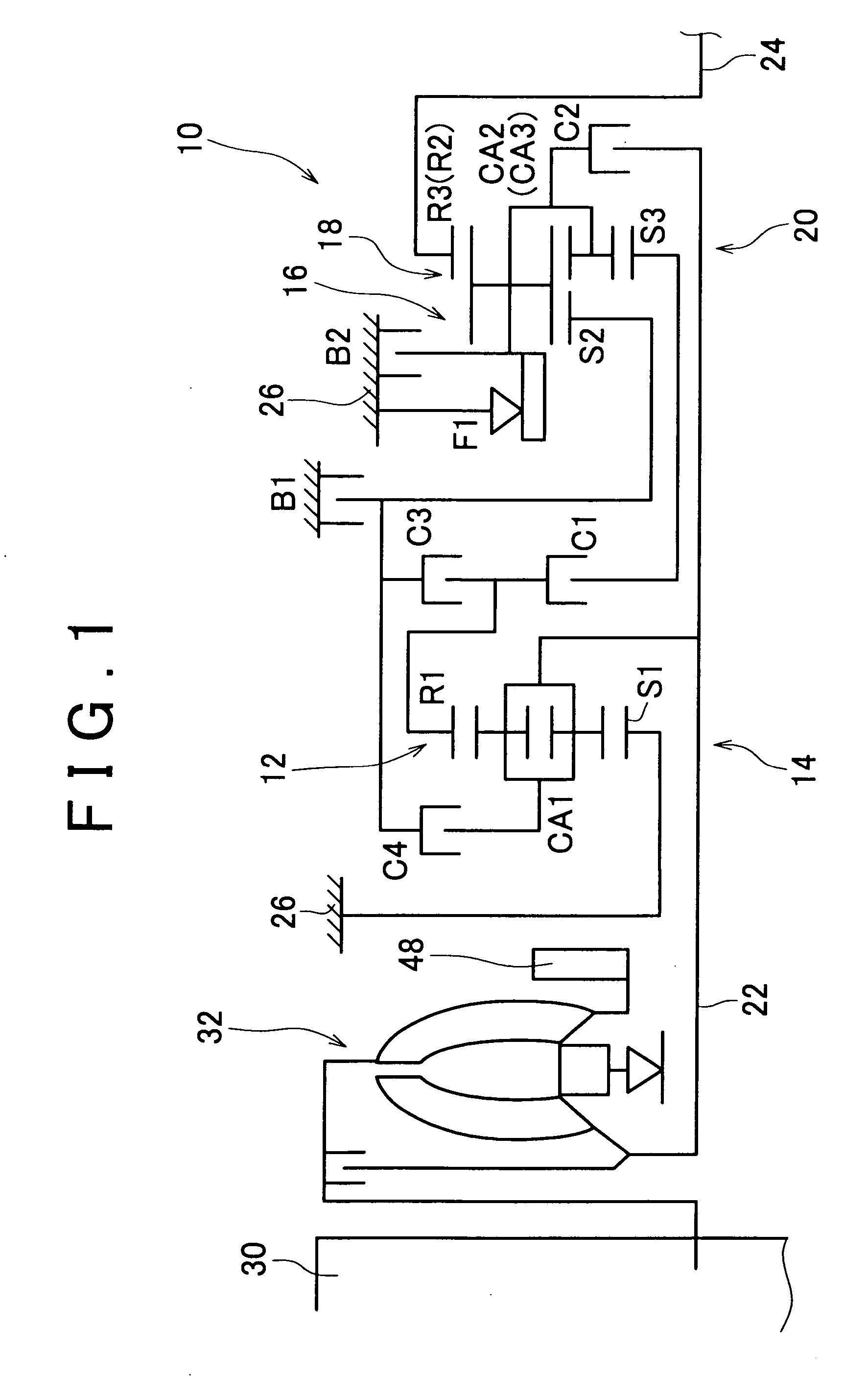
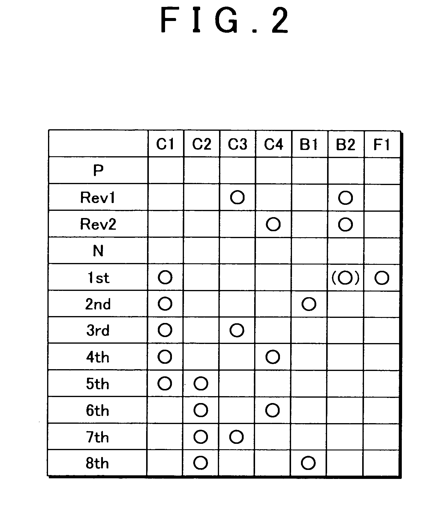
[0035]FIG. 1 is a schematic diagram showing a vehicular automatic transmission 10. FIG. 2 is a table explaining the operating states of engagement elements in the automatic transmission 10 at each of a plurality of shift speeds. The automatic transmission 10 is appropriately disposed in the longitudinal direction of a front-engine rear-drive vehicle. The automatic transmission 10 includes a first shifting portion 14 and a second shifting portion 20 that are disposed on one axis. The first shifting portion 14 includes a first planetary gear unit 12 of a double pinion type. The second shifting portion 20 includes a second planetary gear unit 16 of a single pinion type and a third planetary gear unit 18 of a double pinion type. The rotational speed of an input shaft 22 is changed, and the changed rotational speed is output thro...


PUM


Abstract

In a hydraulic control apparatus for a vehicular automatic transmission, if it is determined that there is a failure that may cause tie-up in an automatic transmission, communication is provided between a first output port and a first drain port in a switching valve. As a result, a hydraulic frictional engagement device, which should be disengaged when there is a failure, is disengaged. Also, a specific shift speed is achieved by controlling the switching valve. Therefore, it is not necessary to select a shift speed that is achieved on the condition that the hydraulic frictional engagement device, which should be disengaged when there is a failure, is engaged. Thus, it is possible to prevent a shift that may impair driveability when there is a failure that may cause tie-up in the automatic transmission.

Description

INCORPORATION BY REFERENCE [0001] The disclosure of Japanese Patent Application No. 2005-223350 filed on Aug. 1, 2005, including the specification, drawings and abstract is incorporated herein by reference in its entirety. BACKGROUND OF THE INVENTION [0002] 1. Field of the Invention [0003] The invention relates to a hydraulic control apparatus for a vehicular automatic transmission in which hydraulic frictional engagement devices are engaged by controlling solenoid valves that output hydraulic pressure directly to the hydraulic frictional engagement devices. More particularly, the invention relates to a technology in which when there is a failure that may cause tie-up in an automatic transmission, a specific shift speed is achieved to prevent tie-up. [0004] 2. Description of the Related Art [0005] Japanese Patent Application Publication No. JP-A-2000-65203 describes an example of a hydraulic control apparatus for a vehicular automatic transmission. In the automatic transmission, a p...

Claims


Application Information

Patent Timeline
Patent Type & Authority Applications(United States)
IPC IPC(8): F16H61/00F16H61/12F16H61/68F16H61/684F16H61/686
CPCF16H61/12F16H61/686F16H2061/1204Y10T477/6937Y10T477/6934Y10T477/69363Y10T477/69F16H2061/1232
Inventor NOZAKI, KAZUTOSHIHONDA, ATSUSHIABE, AKIHARUOTA, HIROFUMI
Owner TOYOTA JIDOSHA KK
Features
  • R&D
  • Intellectual Property
  • Life Sciences
  • Materials
  • Tech Scout
  • Unparalleled Data Quality
  • Higher Quality Content
  • 60% Fewer Hallucinations
Learn More