Apparatus and method for performing display processing, and computer program product

a display method and apparatus technology, applied in the field of display images, can solve the problems of difficulty in performing detailed setting desired by users in the display apparatus, difficulty in enabling users to select a desired function, and inability to achieve detailed setting

Inactive Publication Date: 2007-02-01
RICOH KK
View PDF21 Cites 78 Cited by
  • Summary
  • Abstract
  • Description
  • Claims
  • Application Information

AI Technical Summary

Problems solved by technology

Conventionally, it is difficult to perform detailed setting desired by a user in an apparatus, such as an image forming apparatus, including an operation panel.
Since items displayed in the screen are complicated, it is not easy for the user to select a desired function from the items displayed and set the function.
Those skilled in the art have not made any active proposal concerning a display method for improving operability of the apparatus.
However, the technology for not displaying an item corresponding to an unavailable function in a screen described in the first document simply prevents a user from selecting the unavailable function by mistake.
In other words, it is impossible to improve, using such a display technology, operability in setting input and output functions usually performed.
On the other hand, it is difficult to transfer the display technology provided for a PC described in the second document to an image forming apparatus and the like.
Thus, a size of the liquid crystal touch panel that can be provided in the image forming apparatus is limited.
This problem is present not only in the image forming apparatus but also in an apparatus with a size of a display unit limited because of portability or a place of installation.
In the apparatus in which portability, reduction in space, or other functions are given higher priorities than a size of the display unit such as the liquid crystal touch panel, it is impossible to use the display technology proposed to be used in the PC.
Thus, it is difficult to set functions even if the display technology proposed to be used in the PC is used.
However, it is difficult to designate a position by a unit of several dots when a user manually selects a function using the liquid crystal touch panel.

Method used


Image

  • Apparatus and method for performing display processing, and computer program product
  • Apparatus and method for performing display processing, and computer program product
  • Apparatus and method for performing display processing, and computer program product

Examples


first embodiment

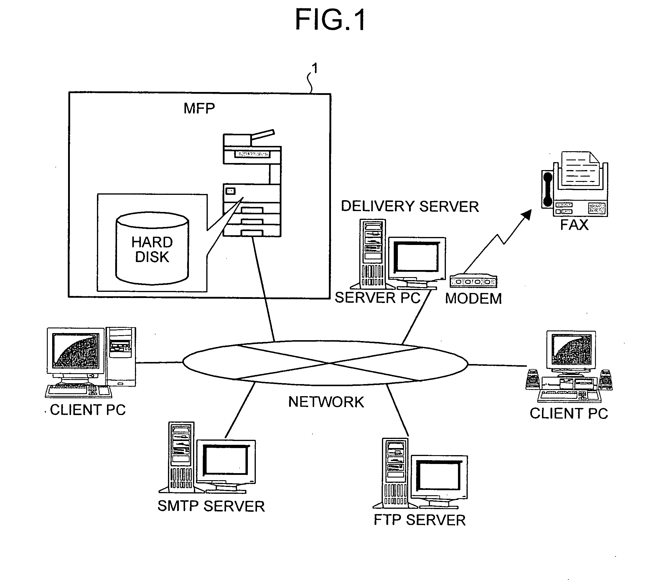
[0076]FIG. 1 is a network diagram for explaining a network environment around an MFP 1 that can execute functions of a display processing apparatus according to the present invention. As shown in the figure, according to the progress of networking in recent years, apparatuses such as personal computers (PCs) provided in an office or the like are usually connected to a network such as a local area network (LAN) and communicate with one another. For example, a client PC, a simple mail transfer protocol (SMTP) server, a file transfer protocol (FTP) server, a server PC, and the like are connected to the network shown in the figure and can transmit and receive electronic mails and transfer files. A delivery server connected to the network by a modem can communicate with a facsimile apparatus outside the office.

[0077] According to such progress in networking, the MFP 1 is also connected to such a network and is capable of communicating with the apparatuses such as the PCs. When the MFP 1 ...

second embodiment

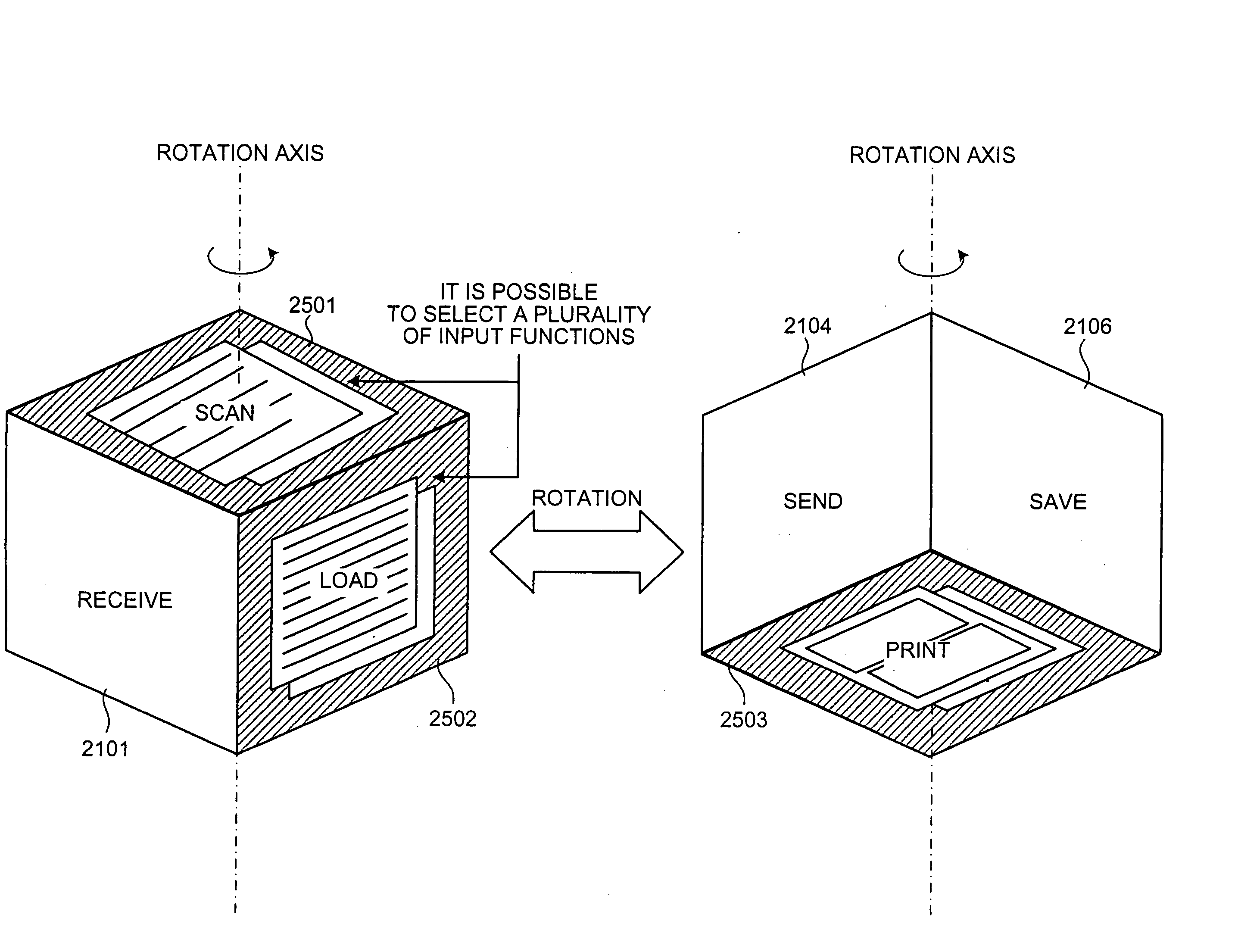
[0166] In the present invention described below, a virtual cube is displayed on the liquid crystal touch panel 320.

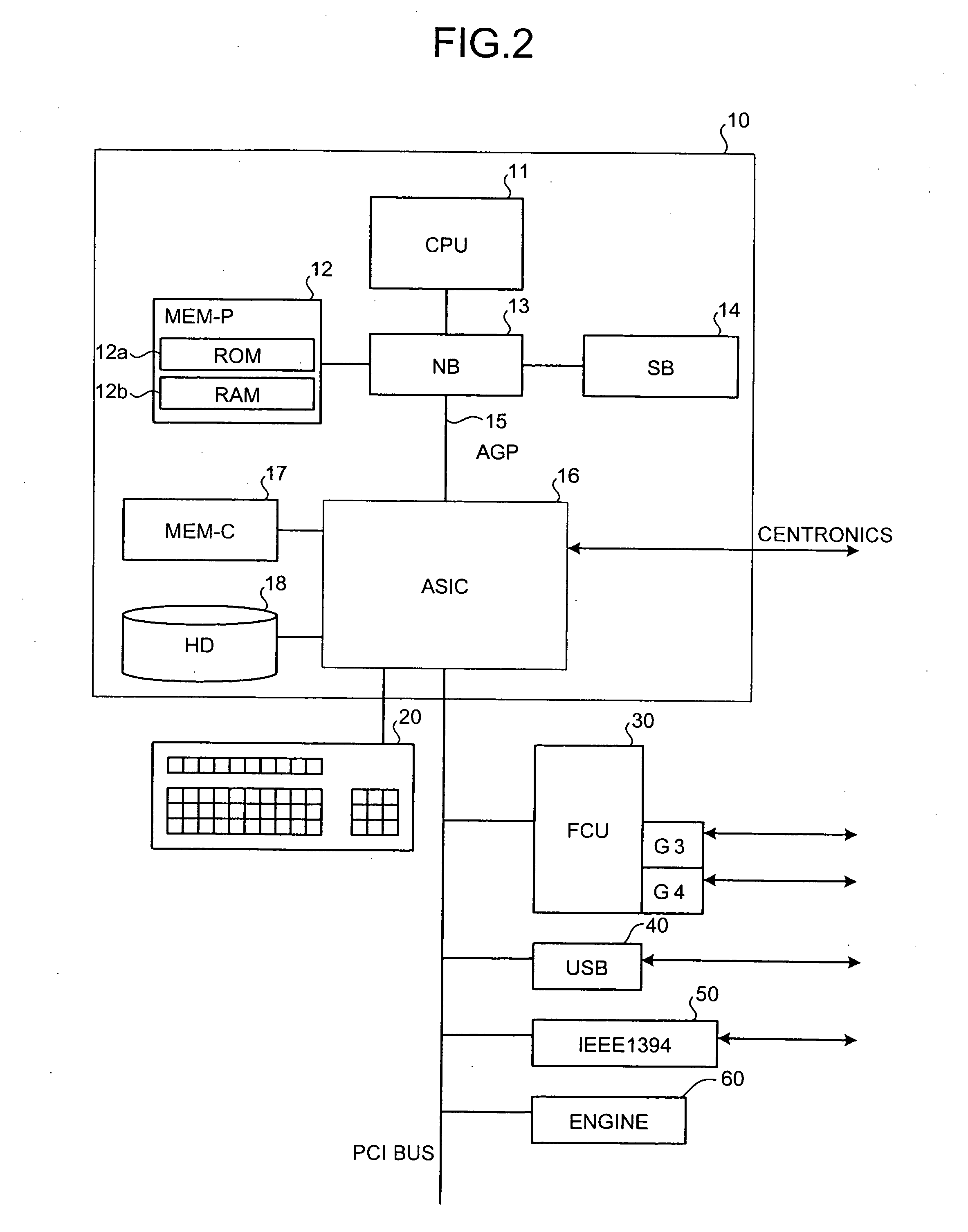
[0167]FIG. 19 is a functional block diagram of an MFP 1900 according to the second embodiment. As shown in the figure, the MFP 1900 is different from the MFP 1 according to the first embodiment in that the application layer 451 is changed to an application layer 1951 that performs different processing. In the following explanation, components identical with those in the first embodiment are denoted by the identical reference numerals and signs. Explanations of the components are omitted.

[0168] The MFP 1900 according to this embodiment includes the same network environment as the MFP 1 according to the first embodiment and includes the operation panel 300 shown in FIG. 3.

[0169] The application layer 1951 is different from the application layer 451 according to the first embodiment in that the display processing unit 401 is changed to a display processing unit 1901 that...

fifth embodiment

[0230]FIG. 49 of the fifth embodiment is a diagram of an example of a screen displayed on the liquid crystal touch panel 320 by the display processing unit according to this modification. As shown in the figure, the display processing unit displays respective virtual cubes by rotating the virtual cubes at predetermined time intervals as in the embodiments described above to switch display of a plurality of surfaces having input function markings shown thereon and display of a plurality of surfaces having output function marking shown thereon.

[0231] When the selection accepting unit accepts selection of a surface having an input function marking shown thereon and a surface having an output function marking shown thereon to customize a virtual cube described in a shortcut space, it is possible to save this virtual cube. Consequently, when the customer logs in again, the display processing unit displays the virtual cube in the saved state. The selection accepting unit accepts selection...


PUM


Abstract

A display processing apparatus includes a display processing unit that displays an input indicating area and an output indicating area. Input functions are displayed in the input indicating area and output functions are displayed in the output indicating area. The output indicating area can be displayed where the input indicating area has been displayed, or vice versa. When a user selects a function from those areas, that function is executed.

Description

CROSS-REFERENCE TO RELATED APPLICATIONS [0001] The present document incorporates by reference the entire contents of Japanese priority document, 2005-223416 filed in Japan on Aug. 1, 2005 and 2005-223417 filed in Japan on Aug. 1, 2005. BACKGROUND OF THE INVENTION [0002] 1. Field of the Invention [0003] The present invention generally relates to displaying an image, specifically relates to displaying only the image in an area of an image. [0004] 2. Description of the Related Art [0005] Conventionally, it is difficult to perform detailed setting desired by a user in an apparatus, such as an image forming apparatus, including an operation panel. This is because, while the apparatus includes a screen of a size only necessary and sufficient for displaying functions for the user and an interface used for the setting includes only a ten key, a touch panel, and the like, all functions that can be set have to be displayed in the screen. Since items displayed in the screen are complicated, it...

Claims


Application Information

Patent Timeline
Patent Type & Authority Applications(United States)
IPC IPC(8): G06F9/00
CPCG06F3/04886G06F2203/04802G03G15/5091G03G2215/00109G03G15/5087G03G15/502
Inventor KATSUYAMA, GORO
Owner RICOH KK
Why Eureka
Try Eureka