Method of manufacturing stone veneers

a technology of stone veneers and veneers, which is applied in the field of stone masonry, can solve the problems of reducing the production efficiency of veneers or pavers, and reducing the production efficiency of stone veneers. the effect of maximizing the output of such corners

Inactive Publication Date: 2007-02-08
MUSKOKA GRANITE & STONE
View PDF15 Cites 1 Cited by
  • Summary
  • Abstract
  • Description
  • Claims
  • Application Information

AI Technical Summary

Benefits of technology

[0009] It is another object of this invention to provide a method of manufacturing that maximizes the output of such corners from a single stone.
[0010] A still further object of this invention is to provide a method of manufacturing veneers that maximizes the amount of veneer or pavers produced from a single stone that has at least one natural, non-saw cut face.
[0011] Another object of the invention is to provide a simple method of applying veneers to a building wall that allows an unskilled worker to perform the task.

Problems solved by technology

Stone that is cut with a saw loses its natural appearance on the surfaces created by the saw cut and those surfaces are not visually appealing.
Another difficulty in the industry is that, when two veneers are used to make a corner, it is visually obvious, because of the seams between the veneers, that thin stone is being used and this is not desirable.
Cutting the stone across the split face requires a saw and is both more difficult and more expensive than splitting stone.
Often, when the stone is split or cut, it may end up less than 1″ think and be unsuitable for use as veneer.

Method used


Image

  • Method of manufacturing stone veneers
  • Method of manufacturing stone veneers
  • Method of manufacturing stone veneers

Examples


Embodiment Construction

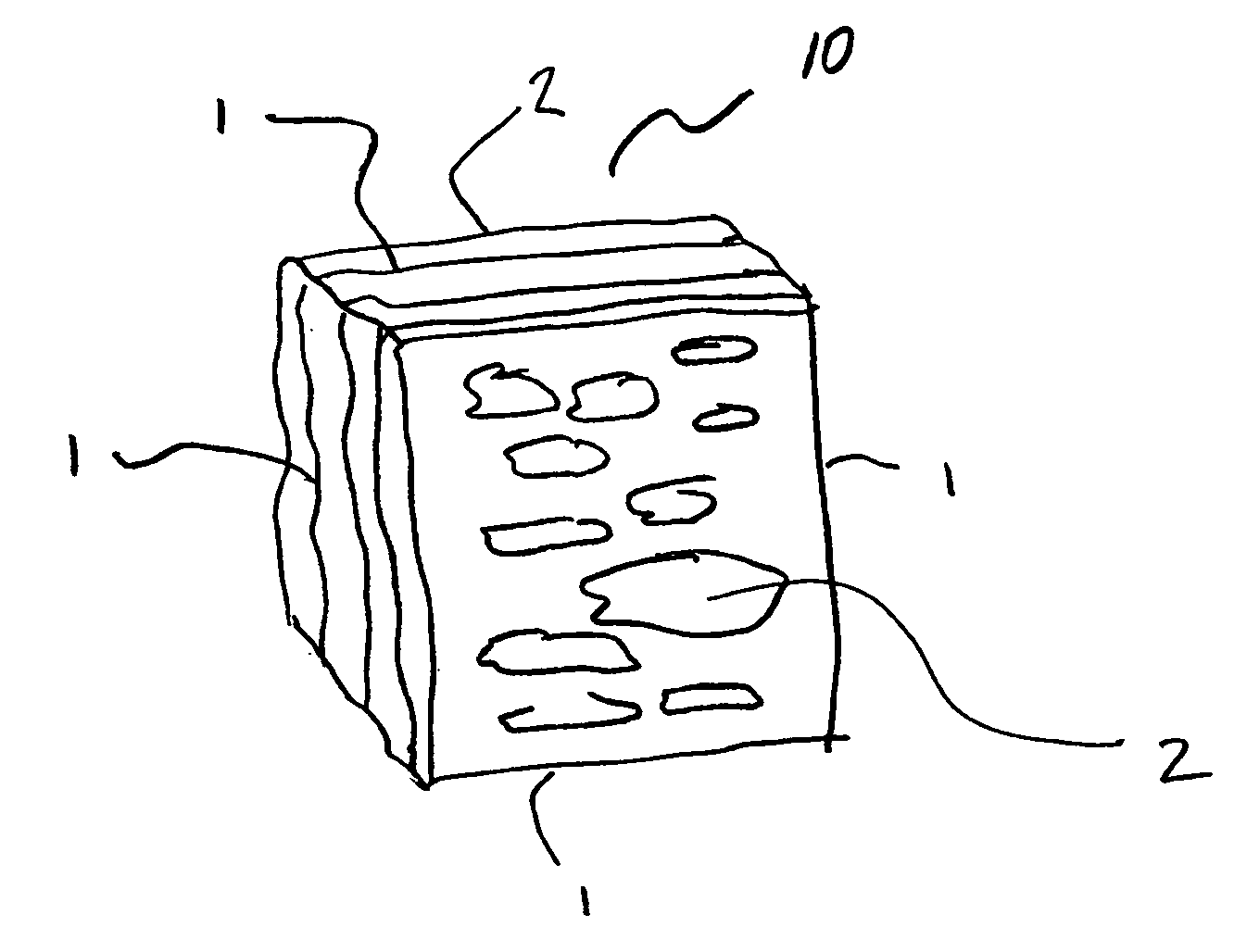
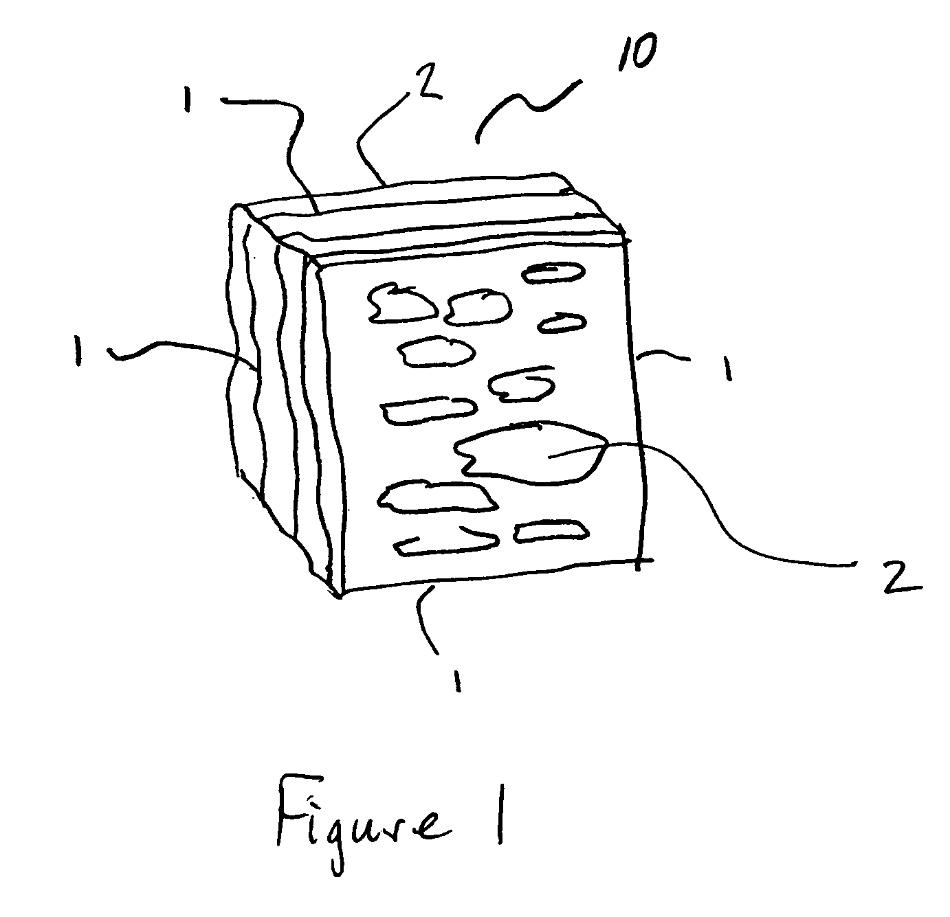
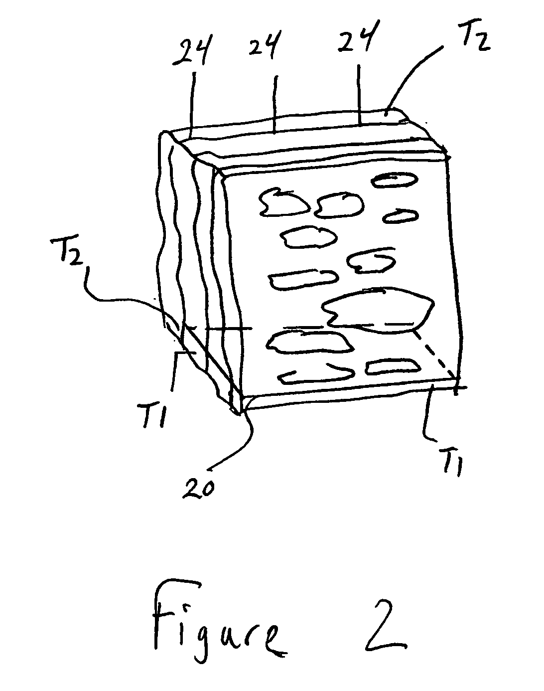
[0024] Referring now to FIG. 1, a typical stone is shown at 10. The side grain or ashler faces are indicated at 1 and the split face is indicated at 2. A presently preferred embodiment of the invention is shown in FIGS. 2 and 3, in which veneer corners 30 of thickness T1 and T2 are produced by making a cut 20 into the stone across the split face 2 to a depth equal to the thickness of the stone, less T1, a desired thickness of the veneer corner, and then splitting the stone from the side planar with the cut, but furthest from it, along a plane 24, distance T2, a desired thickness of the veneer corner, typically, but not necessarily, equal to T1, from the face of the stone opposite the side from which the first cut was made. This process may be repeated a number of times with the remaining stone 34.

[0025] In another presently preferred embodiment, the splitting can be replaced by a second cut along plane 24 that terminates before intersecting the first cut 20. The created overhang su...


PUM

PropertyMeasurementUnit
inside angleaaaaaaaaaa
thicknessaaaaaaaaaa

Abstract

An efficient method of manufacturing stone corner veneers, veneers, floor tiles and pavers, as well as a method of applying the veneers, is disclosed. The method consists of manufacturing veneer corners from a substantially parallelepiped stone, comprising the steps of: a) making a cut from a split face side of the stone into the stone a distance equal to the dimension of the stone from the surface being cut into to the opposite surface of the stone, less a thickness equal to a desired thickness of the veneer corner; and b) splitting the stone, from the side of the stone parallel to the cut and furthest from it, along a grain to the internal end of the cut whereby the veneer corner is created having an ashler side and a split face side and the remaining stone has only one cut face on an ashler side.

Description

FIELD OF THE INVENTION [0001] The present invention relates to the field of stone masonry. In particular, it relates to a method of manufacturing stone veneers, corners and pavers and a method of applying the veneers to buildings. BACKGROUND OF THE INVENTION [0002] Stone has long been used as a construction material for houses and other buildings. Typically, it was quarried and cut into blocks that were laid as structural components of buildings. More recently, due to the costs associated with materials like granite, it has become popular to cut the stone into thin slabs of about one inch in thickness and to apply these slabs or veneers to the exterior of buildings to give the appearance that the buildings are made from stone. [0003] Stone that is cut with a saw loses its natural appearance on the surfaces created by the saw cut and those surfaces are not visually appealing. It is, therefore, beneficial to maximize the amount of veneer created from a single stone that has at least o...

Claims


Application Information

Patent Timeline
Patent Type & Authority Applications(United States)
IPC IPC(8): E04B5/04
CPCB28D1/222E04F15/08E04F13/144B28D1/30
Inventor HENDERSON, JERRY
Owner MUSKOKA GRANITE & STONE
Why Eureka
Try Eureka