Spring-actuated air-brake cylinder for vehicle brake systems

Active Publication Date: 2007-02-08
WABCO EURO BVBA SPRL
View PDF24 Cites 4 Cited by
  • Summary
  • Abstract
  • Description
  • Claims
  • Application Information

AI Technical Summary

Benefits of technology

[0005] Generally speaking, it is an object of the present invention to provide a new spring-actuated air-brake cylinder as the d

Problems solved by technology

Considerable time and effort is needed to assemble this construction, and the spring of the spring actuator must be of relatively heavy design due to the opposing force of the restoring spring.
Relatively large clamping forces are necessary to ensure

Method used


Image

  • Spring-actuated air-brake cylinder for vehicle brake systems
  • Spring-actuated air-brake cylinder for vehicle brake systems
  • Spring-actuated air-brake cylinder for vehicle brake systems

Examples


Example

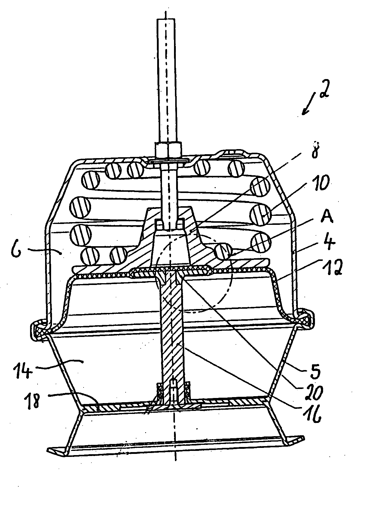
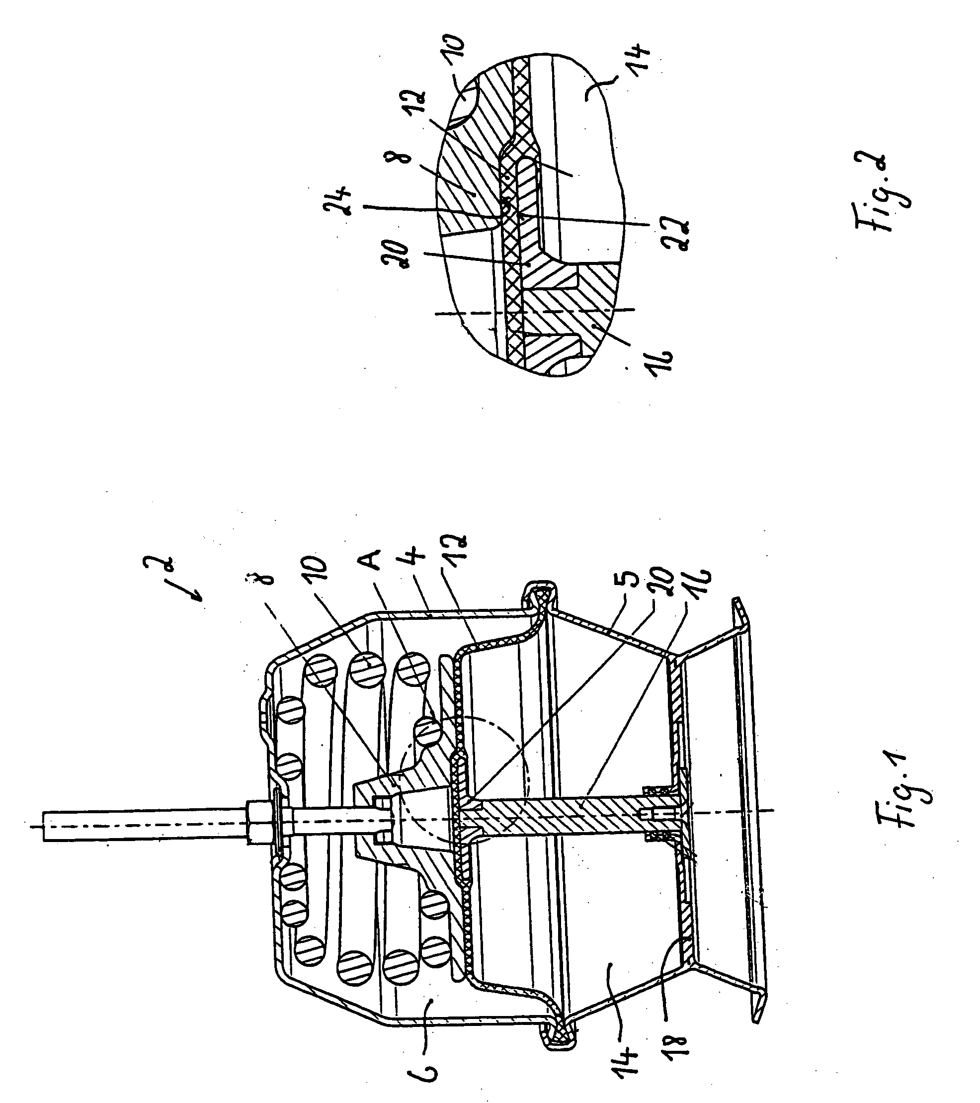
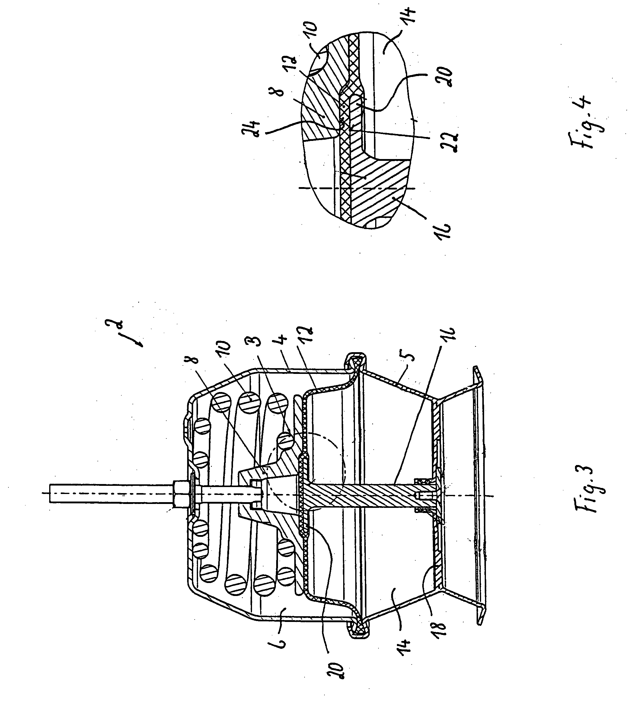
[0021] Referring to the drawing figures, where like reference numerals are used for corresponding parts, FIG. 1 depicts an embodiment of a spring-actuated air-brake cylinder 2 for a motor vehicle having a first housing part 4 and a second housing part 5. An actuator-spring chamber 6 formed in first housing part 4 receives a spring-actuated piston 8 which is acted on by a compression spring 10 as the actuator spring.

[0022] Spring-actuated piston 8 is actively connected to a diaphragm 12. Diaphragm 12 separates actuator-spring chamber 6 from a pressure chamber 14 which is formed in second housing part 5. Diaphragm 12 is circumferentially held (e.g., clamped) sealingly between the two housing parts 4 and 5.

[0023] Inside second housing part 5, a sealed push rod 16 is guided moveably in bottom 18 of housing part 5. On its diaphragm side, push rod 16 is provided with a plate-like pressure member 20 which is fastened (e.g., screwed) onto push rod 16 (see FIG. 1) or is formed in one piece...


PUM


Abstract

A spring-actuated air-brake cylinder as the diaphragm cylinder for vehicle brake systems includes a diaphragm, an actuator-spring chamber in which there is received a spring-actuated piston, which is acted on by a compression spring as the actuator spring and is actively connected to the diaphragm, which is disposed between the actuator-spring chamber and a pressure chamber, in which there is guided moveably a sealed push rod, which can include a pressure member on its diaphragm side. The spring-actuated diaphragm is connected to the push rod or to the pressure member or to the spring-actuated piston by means of vulcanization.

Description

BACKGROUND OF THE INVENTION [0001] The present invention relates generally to a spring-actuated air-brake cylinder as the diaphragm cylinder for vehicle brake systems. [0002] U.S. Pat. No. 5,067,391 describes a spring-actuated air-brake cylinder with diaphragm cylinder wherein there is provided, in the pressure chamber of the spring actuator, a restoring spring that acts on a pressure plate connected by threaded means to a push rod and that presses the diaphragm against a piston plate. Considerable time and effort is needed to assemble this construction, and the spring of the spring actuator must be of relatively heavy design due to the opposing force of the restoring spring. [0003] U.S. Pat. No. 5,507,217 describes a spring-actuated air-brake system with diaphragm cylinder wherein the diaphragm is provided with a central aperture via which the diaphragm can be connected securely to a push rod by means of perforated disks which can be disposed on both sides of the aperture and of a ...

Claims


Application Information

Patent Timeline
IPC IPC(8): F01B7/00F16D65/28
CPCB60T17/088
Inventor SCHRADER, FRANKBRANDT, OLIVEREWALD, JURGENMATTHIAS, WILFRIEDRICHTER, ANDREAS
Owner WABCO EURO BVBA SPRL
Why Eureka
Try Eureka