
Illumination unit for fundus cameras and/or ophthalmoscopes

a technology of ophthalmoscope and camera, which is applied in the field of ophthalmoscope, can solve the problems of deviating from the principle of conventional fundus camera, and achieve the effect of minimizing discomfort and risk to patients, and improving the observation and documentation of the ocular fundus

Inactive Publication Date: 2007-02-08
CARL ZEISS MEDITEC AG
View PDF9 Cites 17 Cited by
  • Summary
  • Abstract
  • Description
  • Claims
  • Application Information

AI Technical Summary

Benefits of technology

[0012] It is the primary object of the present invention to improve the observation and documentation of the ocular fundus by means of an ophthalmologic device, particularly a fundus camera, in such a way that the discomfort of and risk to the patient can be minimized.
[0017] The diagnosis of diseases of the ocular fundus can be considerably facilitated for both the examiner and the patient by a fundus camera based on the fundamental inventive idea.

Problems solved by technology

However, the illumination principle used for this purpose deviates from that of a conventional fundus camera.

Method used


Image

  • Illumination unit for fundus cameras and/or ophthalmoscopes
  • Illumination unit for fundus cameras and/or ophthalmoscopes
  • Illumination unit for fundus cameras and/or ophthalmoscopes

Examples


Embodiment Construction

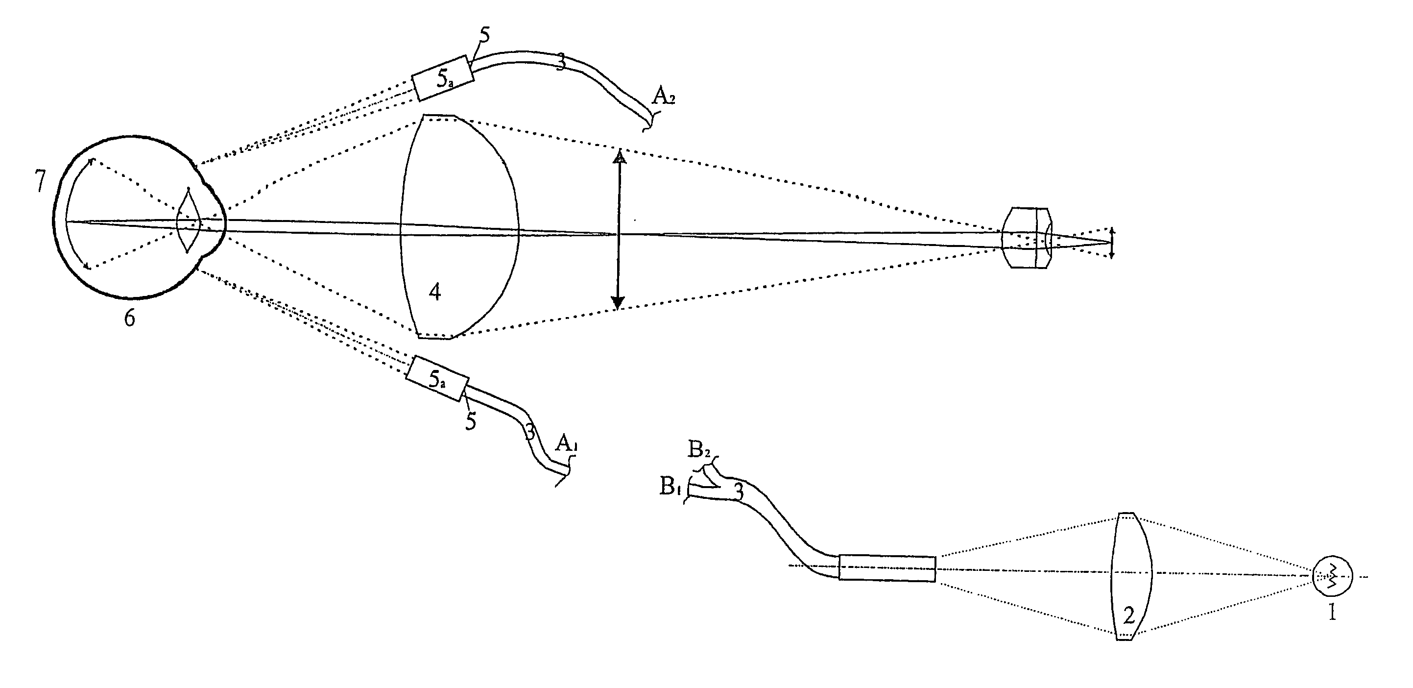
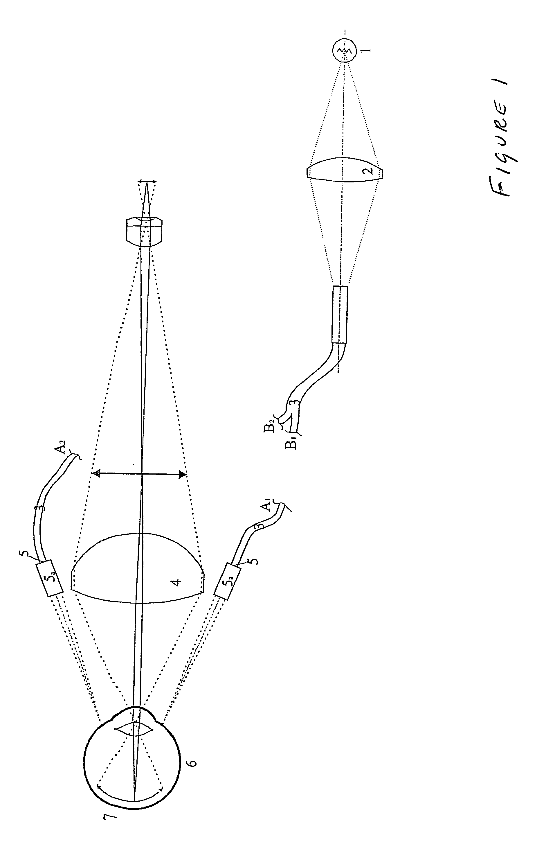
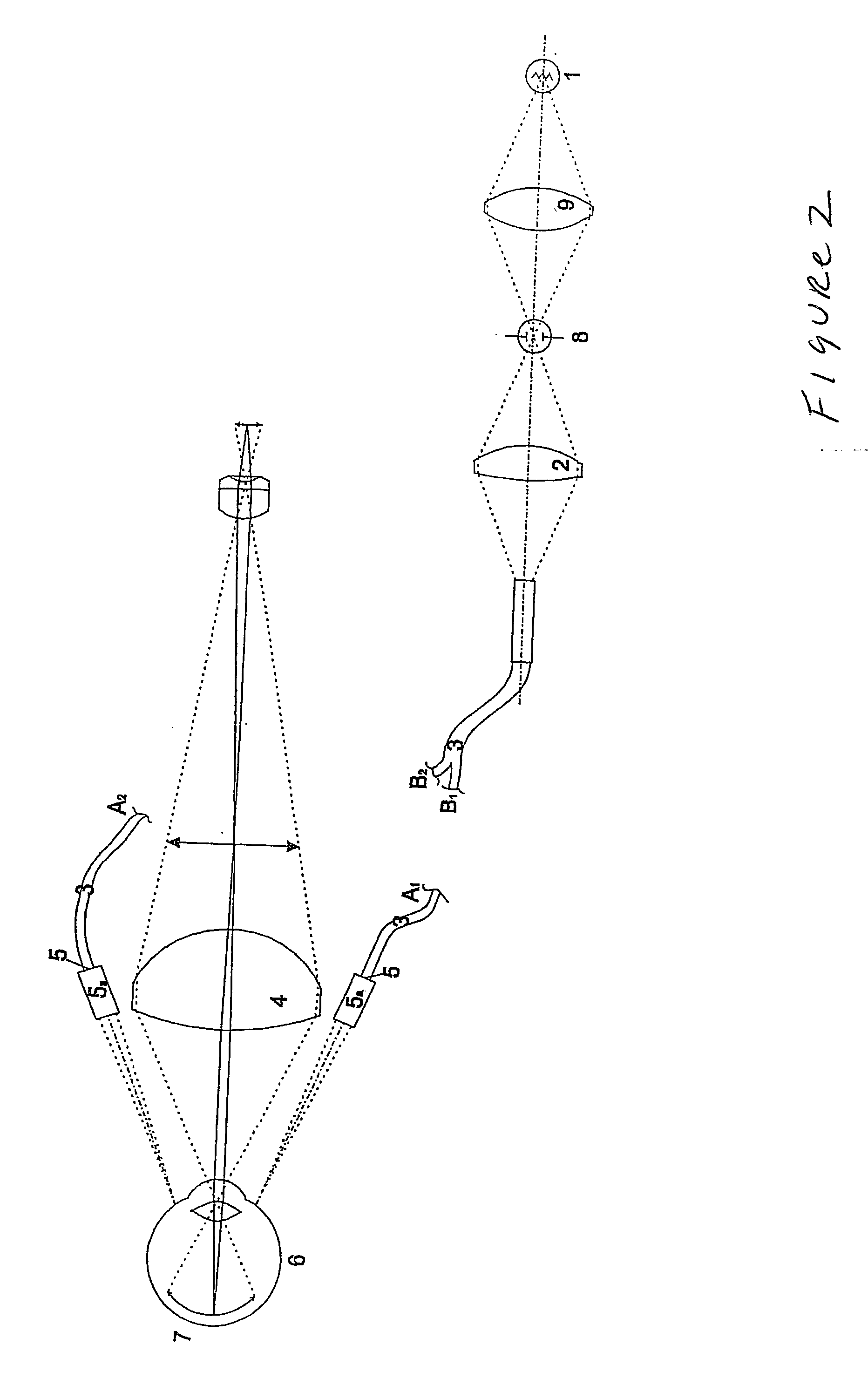
[0022] The illumination unit, according to the invention, for fundus cameras and / or ophthalmoscopes serves to generate a uniform illumination of the fundus by transillumination of the sclera. FIG. 1 shows a top view of the basic construction of a fundus camera with the illumination unit according to the invention. The light emitted by the illumination source 1 is coupled by optical means 2 into light-conducting fibers 3 which extend to the area of the front lens 4 of the fundus camera or ophthalmoscope and whose fiber ends 5 are formed in such a way that the exit faces are projected by means of an optical system 5a onto the sclera of the eye 6 being examined and transilluminate the sclera. However, it is also possible, in principle, to use bundles of light-conducting fibers 3.

[0023] At least two individual light-conducting fibers 3 or bundles of light-conducting fibers 3 are preferably provided and arranged in such a way that the light emitted by the illumination source 1 penetrate...


PUM


Abstract

The present invention is directed to an optical device for the observation and documentation of the ocular fundus and is preferably provided for fundus cameras. In order to generate a uniform illumination of the fundus by transillumination of the sclera in the illumination unit, according to the invention, for fundus cameras and / or ophthalmoscopes, the light emitted by the illumination source is coupled into individual light-conducting fibers or bundles of light-conducting fibers which extend into the area of the front lens of the fundus camera and ophthalmoscope and whose fiber ends are formed in such a way that the exiting light is projected on and transilluminates the sclera. The discomfort caused to the patient by pupil-dilating means is avoided as are the risks associated with the placement of contact lenses. Another substantial advantage of the illumination unit according to the invention is the extremely uniform, large-area illumination of the fundus, so that a correspondingly large visual field of the fundus can be observed and also documented.

Description

CROSS-REFERENCE TO RELATED APPLICATIONS [0001] This application claims priority of International Application No. PCT / EP2004 / 011684, filed Oct. 16, 2004 and German Application No. 103 49 091.4, filed Oct. 22, 2003, the complete disclosures of which are hereby incorporated by reference.BACKGROUND OF THE INVENTION [0002] a) Field of the Invention [0003] The present invention is directed to an optical device with electronic or photographic image sensors for observing and documenting the ocular fundus. The device is preferably provided for fundus cameras and / or ophthalmoscopes. The diagnosis of diseases of the ocular fundus can be considerably facilitated in this way both for the examiner and for the patient. [0004] b) Description of the Related Art [0005] In most of the fundus cameras known from the art, illumination, observation and / or documentation is carried out through the pupil of the eye of the patent being examined. For this purpose, the pupil is always dilated to a certain exten...

Claims


Application Information

Patent Timeline
IPC IPC(8): A61B3/14A61B3/12
CPCA61B3/12
Inventor BIERNAT, DETLEFMOHRHOLZ, UWETEIGE, FRANK
Owner CARL ZEISS MEDITEC AG
Learn More