Low vacuum scanning electron microscope

Inactive Publication Date: 2006-01-19
HITACHI SCI SYST LTD
View PDF8 Cites 20 Cited by
  • Summary
  • Abstract
  • Description
  • Claims
  • Application Information

AI Technical Summary

Benefits of technology

[0011] A positive voltage (0 to 300 V, for example) is applied between the second sample chamber and the sample to accelerate secondary electrons occurring on the sample surface and the secondary ions are allowed to impinge against gas molecules remaining in the sample chamber to generate cascade-wise ionization. Positive (+) ions generated in this instance are detected as absorption current and an image is formed. A relatively high negative voltage of −0.5 to −9 kV, for example, that decelerates the electrons immediately before the sample, is applied between the first and second sample chambers. The incident electron beam forms a thin electron beam under a small lens aberration condition while keeping

Problems solved by technology

Therefore, the mean free path of the incident electrons becomes shorter and scattering occurs, thereby inviting the problems that S/N of the image gets deteriorated and resolution drops in the observation by the low vacuum scanning electron microscope.
However, particularly because it is difficult to acquire high resolution and S/N at a low acceleration voltage, it has still been difficult to grasp with fidelity the surface structure of the sample.
In the existing low vacuum secondary electron detection methods, the signal amount becomes markedly small due to the impingement with the gas molecules inside the sample chamber in the

Method used


Image

  • Low vacuum scanning electron microscope
  • Low vacuum scanning electron microscope
  • Low vacuum scanning electron microscope

Examples


Embodiment Construction

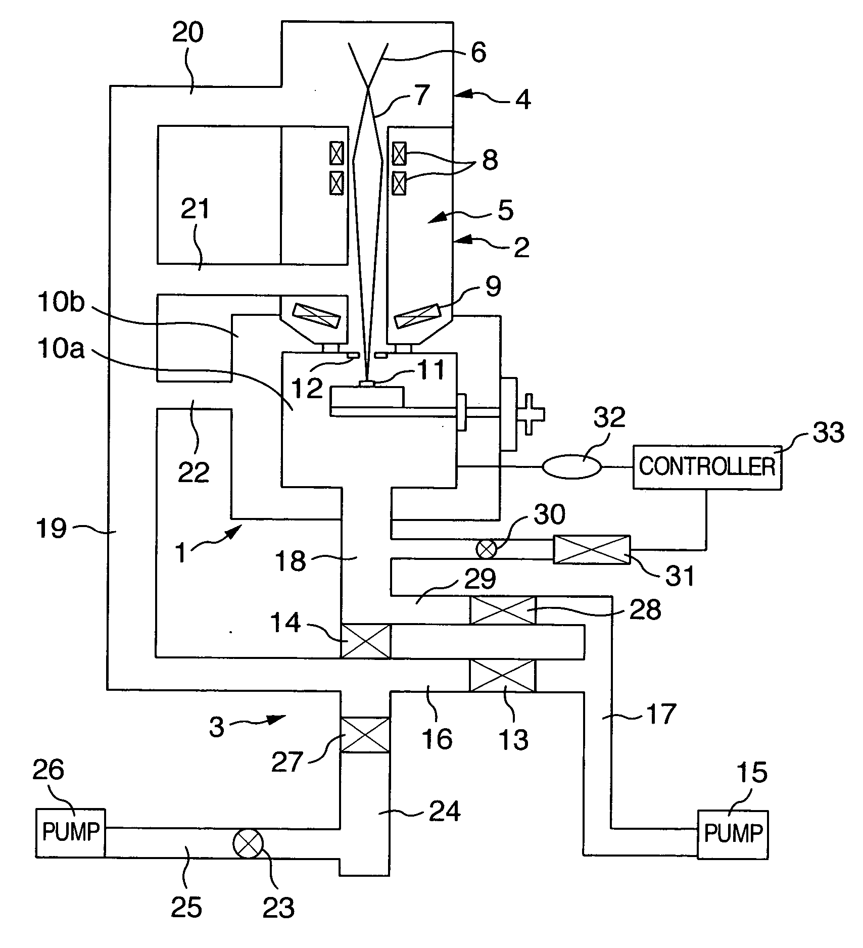
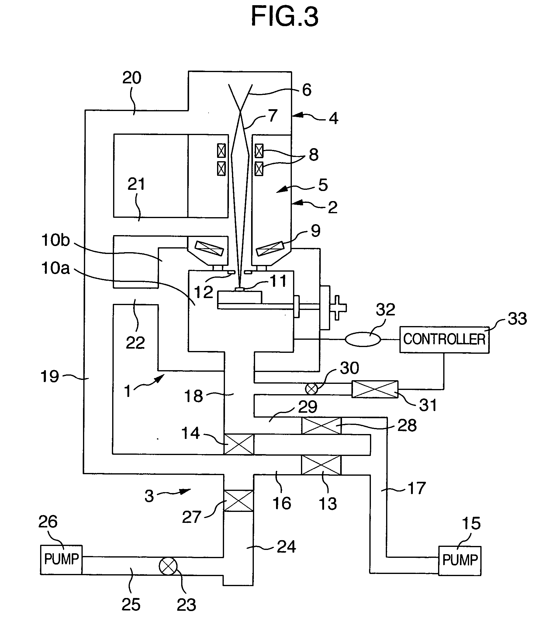
[0020]FIG. 3 is a schematic view showing a low vacuum scanning electron microscope according to an embodiment of the invention. The scanning electron microscope includes a sample chamber 1, a barrel portion 2 at an upper stage of the sample chamber 1 and an exhaust system 3 for exhausting the inside of each of the sample chamber 1 and the barrel portion 2. The barrel portion 2 includes an electron gun portion 4 and a lens system (electronic optical system) portion 5. The sample chamber 1 has a double structure of an inner sample chamber 10a and an outer sample chamber 10b that can independently conduct the exhaust operation.

[0021] An electron gun 6 such as a thermo-electron gun or a Schottky emission type electron gun is disposed in the electron gun portion 4. The electron beam 7 emitted from the electron gun 6 and accelerated is thinly converged by a condenser lens 8 and an objective lens 9 inside the lens system portion 5 and is irradiated to a sample 11 arranged inside the inner...


PUM


Abstract

High resolution observation is achieved at a low acceleration voltage of 5 kV or below under a high pressure condition of a sample chamber. A sample chamber has a double structure and an inner sample chamber for keeping low vacuum is arranged inside an outer sample chamber having high vacuum. A relatively high negative voltage such as −1 to −9 kV for decelerating electrons immediately before a sample is applied between the outer sample chamber and the inner sample chamber. When an incident electron beam passes through an objective lens, an electron beam keeping high energy and having small aberration is formed and is decelerated immediately before the sample to acquire high resolution at a low acceleration voltage.

Description

BACKGROUND OF THE INVENTION [0001] 1. Field of the Invention [0002] This invention relates to a low vacuum scanning microscope that keeps the inside of a sample chamber at lower vacuum than a barrel portion, reduces charge-up of an insulator sample and conducts quick observation of a water-containing sample by omitting a pre-processing. [0003] 2. Description of the Related Art [0004] When observation is made by keeping the inside of a sample chamber at a higher pressure (about 1 to about 300 Pa, for example) than at other portions in a low vacuum scanning electron scope, it is customary to detect reflected electrons and to form an image. In the sample chamber kept at a high pressure, however, the probability of impingement between incident electrons and remaining gas molecules inside the sample chamber becomes higher with the increase of the pressure of the sample chamber. Therefore, the mean free path of the incident electrons becomes shorter and scattering occurs, thereby inviting...

Claims


Application Information

Patent Timeline
IPC IPC(8): G21K7/00
CPCH01J37/28H01J2237/04756H01J2237/2608H01J2237/2538H01J2237/188
Inventor NISHIMURA, MASAKOYAMADA, MITSUHIKO
Owner HITACHI SCI SYST LTD
Why Eureka
Try Eureka