Composite Triangular-Pyramidal Cube-Corner Retroreflective Sheeting And Retroreflective Articles

a triangular-pyramidal cube and corner retroreflective technology, applied in the field of composite triangular-pyramidal cubecorner retroreflective sheeting of novel structure and retroreflective articles, can solve the problems of inconvenient practical application of retroreflective light with excessively narrow divergence angle, and the defect of inferior retroreflectivity of retroreflective sheeting and retroreflective articles using triangular-pyramidal cub

Inactive Publication Date: 2009-05-14
NIPPON CARBIDE KOGYO KK
View PDF11 Cites 23 Cited by
  • Summary
  • Abstract
  • Description
  • Claims
  • Application Information

AI Technical Summary

Benefits of technology

[0030]The invention achieves the improvements in entrance angularity, observation angularity and azimuth angularity over those of heretofore known retroreflective elements, with use of composite cube-corner retroreflective elements in which groups of each at least two triangular-pyramidal cube-corner retroreflective elements which are each defined by three lateral faces mutually crossing at approximately right angles, as being configured by three-directional V-shaped parallel groove groups having substantially symmetrical sections and intersecting with each other, and which are arrayed in the closest-packed state, projecting on one side of their common sub-plane (SH-SH), each of said groups of sub-retroreflective elements being disposed on one main retroreflective element which is defined by three lateral faces mutually crossing at approximately right angles, as being configured by three-directional V-shaped parallel groove groups having substantially symmetrical sections and intersecting with each other, and which is disposed on the main plane (S-S). Use of such composite elements promotes, in particular, improvement in observation angularity.
[0031]Above-described improvements are furthermore achieved by use of above-described composite cube-corner retroreflectice elements in which the sub-plane (SH-SH) and the main plane (S-S) are in parallel. Particularly, use of such composite elements promotes improvement in observation angularity.
[0032]Above-described improvements are also achieved by use of above-described composite cube-corner retroreflective elements in which the optical axes of the sub-reflective elements and / or the main reflective elements are tilted. Adoption of such composite elements particularly promotes improvement in entrance angularity.
[0033]Use of above-described composite cube-corner retroreflective elements in which, among the base lines in the three directions which define the main reflective element and the base lines in other three directions which define the sub-reflective elements, the directions of at least one set of the base lines are not in parallel, and preferably directions of that set of the base lines are right angled, also achieves the objects of the present invention and promotes improvement particularly in azimuth angularity.
[0034]Furthermore, such improvements in all of the entrance angularity, observation angularity and azimuth angularity can be effectively accomplished by combining the invention with known improving techniques as referred to in the above.
[0035]Those triangular-pyramidal cube-corner retroreflective sheetings and retroreflective articles comprising the composite cube-corner retroreflective elements according to the present invention exhibit excellent entrance angularity, observation angularity and azimuth angularity which cannot be expected of heretofore known retroreflective elements.

Problems solved by technology

Whereas, retroreflective sheetings and retroreflective articles using triangular-pyramidal cube-corner retroreflective elements are generally subject to a defect of inferior entrance angularity, because the light rays entering into their reflective lateral faces at the angles less than the critical angle that satisfies the total internal reflection condition determined by the ratio of the refractive index of individual transparent medium constituting retroreflective elements to the refractive index of ambient air, are not totally reflected at interfaces of the reflective lateral faces but are transmitted to the backs of the reflective lateral faces.
That is, while they exhibit favorable retroreflectivity within a range at which the entrance angle formed between the retroreflective sheeting surface and incident light is small, there is a problem that the retroreflectivity rapidly drops with increase in the entrance angle.
Nevertheless, retroreflected light with excessively narrow divergence angle is apt to invite inconvenience in its practical application, e.g., when light rays emitted from head lamps of a car are retroreflected by a traffic sign, the retroreflected light is difficult to reach the eyes of the person driving the car, at positions deviating from the optical axis of the light.
Such an inconvenience is particularly enhanced as the distance between the car and the traffic sign is shortened, because of the increase in the observation angle, which is defined as an angle formed between the incident axis of the light and the observation axis connecting the driver and the point of reflection.
That is, heretofore known triangular-pyramidal cube-corner retroreflective elements in general are subject to the problem of inferior observation angularity.
Thus, triangular-pyramidal cube-corner retroreflective elements have a problem of dependency of their retroreflective performance on azimuth angle, i.e., a problem in azimuth angularity.
Said US patent to Jungersen, however, contains no specific disclosure about extremely small size triangular-pyramidal reflective elements as described later, or no disclosure or suggestion about the desirable size or tilt in optical axis of triangular-pyramidal reflective elements for exhibiting excellent observation angularity or entrance angularity.
However, because the above proposal by Stamm provides a specular layer on reflective sides as a means to improve wide angularity, such drawbacks as that appearance of the formed retroreflective sheeting and retroreflector is apt to become dark, or the metal used for the specular layer such as aluminum or silver is oxidized during use by infiltrated water or air, which leads to occasional decrease in reflective performance.
Furthermore, this patent is entirely silent on the means for improving wide angularity by tilting optical axes.
Such periodical change in adjacent V-shaped groove angles, however, increases difficulty in mold processing.
Even if the difficulty could be overcome, number of possible combinations of the deflections is limited and cannot provide uniform spreading of reflected light.
Whereas, it is extremely difficult to manufacture such processing tools having curved sections and hence it is very difficult to obtain quadratic surfaces according to an intended design, due to the difficulty in obtaining the tools.
Such retroreflective sheets and articles constructed of triangular-pyramidal reflective elements with their bases positioned on a same plane are invariably inferior in entrance angularity, i.e., they are subject to a defect that retroreflective performance rapidly drops with increased entrance angle of light rays entering into the triangular-pyramidal reflective elements.
Also those known U.S. Pat. No. 4,775,219 to Appeldorn, U.S. Pat. No. 5,171,624 to Walter, and U.S. Pat. No. 5,565,151 to Nilsen proposed improvement in observation angularity by various means as above-described, but all of the inventions have the shortage that manufacturing of tools therefor or mold processing are difficult.

Method used


Image

  • Composite Triangular-Pyramidal Cube-Corner Retroreflective Sheeting And Retroreflective Articles
  • Composite Triangular-Pyramidal Cube-Corner Retroreflective Sheeting And Retroreflective Articles
  • Composite Triangular-Pyramidal Cube-Corner Retroreflective Sheeting And Retroreflective Articles

Examples


example 1

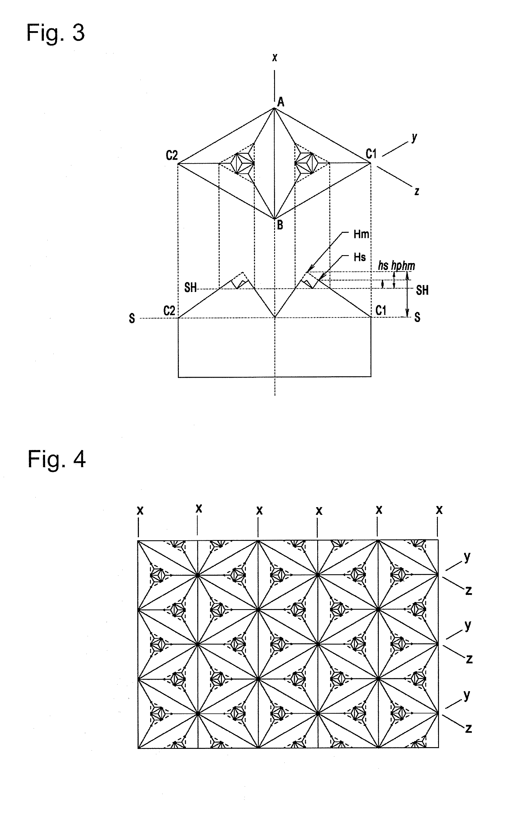
[0101]A composite retroreflective element of the configuration as illustrated in FIG. 3 wherein, on a main reflective element having an optical axis with an angle of tilt of +7° and a distance (hm) from the imaginary apex (Hm) at which the three reflective lateral faces forming the main reflective element would cross with each other, to the main plane (S-S) of 130 μm, a group of four sub-reflective elements were arrayed, each having an optical axis with an angle of tilt of +7° and a height (hs) of 30 μm, was prepared by the same method as used in Comparative Example 1.

[0102]The ratio (hs / hm) of the distance (hs) from the apex (Hs) of the sub-reflective element to the sub-plane (SH-SH) to the distance (hm) from the imaginary apex (Hm) of the main reflective element to the main plane (S-S) in the composite reflective element was 0.23, the distance (hp) from the imaginary apex (Hm) of the main reflective element to the sub-reflective plane (SH-SH) was 50 μm, and the ratio (hp / hm) was 0...

example 2

[0104]A composite retroreflective element of the configuration as illustrated in FIG. 6 wherein, on a main reflective element having an optical axis with an angle of tilt of +7° and a distance (hm) from the imaginary apex (Hm) at which the three reflective lateral faces forming the main reflective element would cross with each other, to the main plane (S-S) of 130 μm, a group of sixteen sub-reflective elements were arrayed, each having an optical axis with an angle of tilt of +7° and a height (hs) of 30 μm, was prepared by the same method as used in Comparative Example 1.

[0105]The ratio (hs / hm) of the distance (hs) from the apex (Hs) of the sub-reflective element to the sub-plane (SH-SH) to the distance (hm) from the imaginary apex (Hm) of the main reflective element to the main plane (S-S) in the composite reflective element was 0.23, the distance (hp) from the imaginary apex (Hm) of the main reflective element to the sub-reflective plane (SH-SH) was 65 μm, and the ratio (hp / hm) wa...

example 3

[0107]A composite retroreflective element of the configuration as illustrated in FIG. 9 wherein, on a main reflective element having an optical axis with an angle of tilt of −6° and a distance (hm) from the imaginary apex (Hm) at which the three reflective lateral faces forming the main reflective element would cross with each other, to the main plane (S-S) of 180 μm, a group of four sub-reflective elements were arrayed, each having an optical axis with an angle of tilt of −6° and a height (hs) of 70 μm, was prepared by the same method as used in Comparative Example 1. Because the four sub-reflective elements had slightly different heights, the distance between the apex of the central, highest sub-reflective element and the sub-plane (SH-SH) was chosen as the height hs.

[0108]The ratio (hs / hm) of the distance (hs) from the apex (Hs) of the sub-reflective element to the sub-plane (SH-SH) to the distance (hm) from the imaginary apex (Hm) of the main reflective element to the main plane...


PUM


Abstract

Adoption of composite cube-corner retroreflective elements in which groups of each at least two sub-retroreflective elements which are each defined by three lateral faces mutually crossing at approximately right angles, as being configured by three-directional V-shaped parallel groove groups having substantially symmetrical sections and intersecting with each other, and which are arrayed in the closest-packed state, projecting on one side of their common sub-plane (SH-SH), each of said groups of sub-reflective elements being disposed on one main retroreflective element which is defined by three lateral faces mutually crossing at approximately right angles, as being configured by three-directional V-shaped parallel groove groups having substantially symmetrical sections and intersecting with each other, and which is disposed on the main plane (S-S).

Description

TECHNICAL FIELD[0001]This invention relates to a composite triangular-pyramidal cube-corner retroreflective sheeting of novel structure and retroreflective articles. More specifically, the invention relates to a cube-corner retroreflective sheeting on which triangular-pyramidal reflective elements of novel structure are arrayed in the closest-packed state, and to the retroreflective articles.[0002]In particular, the invention relates to cube-corner retroreflective sheeting and retroreflective articles comprising triangular-pyramidal cube-corner retroreflective elements (which may be hereafter referred to simply as triangular-pyramidal reflective elements), which are useful for signs such as road signs (common traffic signs, delineators), road surface signs (pavement marker), construction signs and the like; number plates on vehicles such as automobiles, motorcycles and the like; safety materials such as reflective tapes stuck on bodies of tracks, trailers and the like, clothing, lif...

Claims


Application Information

Patent Timeline
Patent Type & Authority Applications(United States)
IPC IPC(8): G02B5/124E01F9/50E01F9/506E01F9/524E01F9/608E01F9/615E01F9/619
CPCG02B5/124
Inventor MIMURA, IKUO
Owner NIPPON CARBIDE KOGYO KK
Why Eureka
Try Eureka