Electronic fingerprint sensor with differential noise cancellation

a fingerprint sensor and differential noise cancellation technology, applied in pulse technique, contact members penetrating/cutting insulation/cable strands, instruments, etc., can solve problems such as parasitic coupling and nois

Active Publication Date: 2007-02-08
SYNAPTICS INC +1
View PDF36 Cites 123 Cited by
  • Summary
  • Abstract
  • Description
  • Claims
  • Application Information

AI Technical Summary

Problems solved by technology

Fingerprint sensors of this type provide satisfactory performance but are subject to parasitic coupling and noise combined with interference coupled through the body of the finger from finger ridges outside the sensor gap.

Method used


Image

  • Electronic fingerprint sensor with differential noise cancellation
  • Electronic fingerprint sensor with differential noise cancellation
  • Electronic fingerprint sensor with differential noise cancellation

Examples


Embodiment Construction

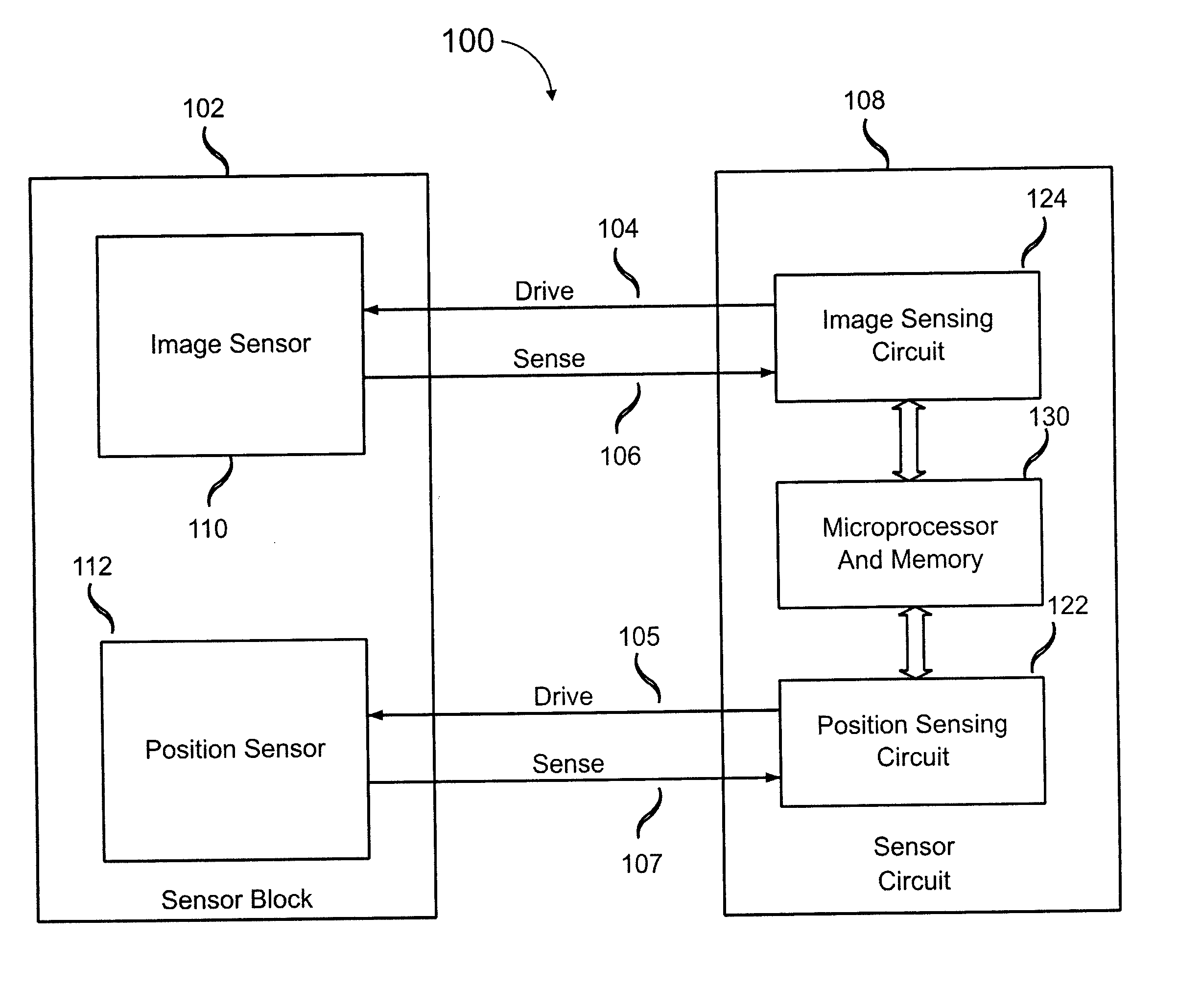
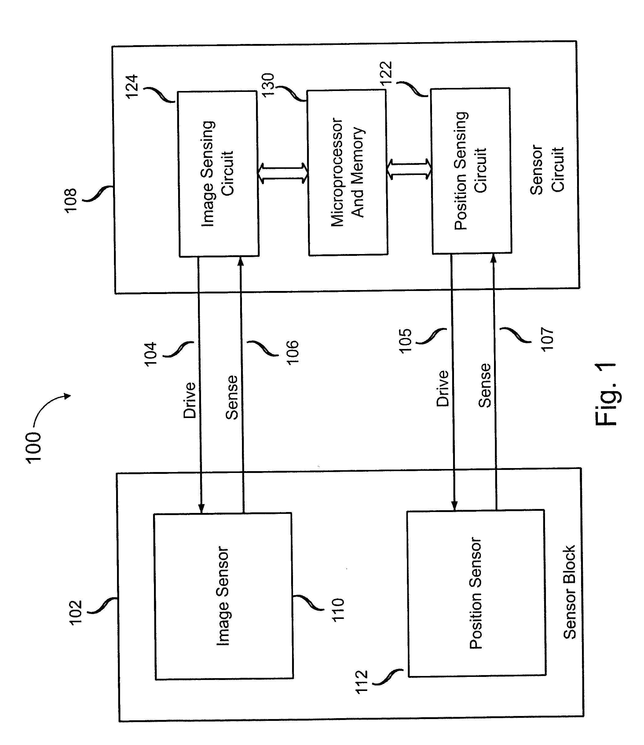
[0017]FIG. 1 shows a fingerprint sensing system 100 incorporating features of the present invention. A sensor block 102 receives drive signals from and delivers sense signals to a sensor circuit 108. Sensor block 102 includes an image sensor 110 and a position sensor 112. Image sensor 110 and position sensor 112 may be fabricated on a single substrate as described below. Sensor circuit 108 includes an image sensing circuit 124, a position sensing circuit 122 and a microprocessor and memory 130. Image sensor 110 receives drive signals 104 from and delivers sense signals 106 to image sensing circuit 124. Position sensor 112 receives drive signals 105 from and delivers sense signals 107 to position sensing circuit 122. Microprocessor and memory 130 acquires and processes image data and position data and controls operation of the system. The components of fingerprint sensing system 100 are described below.

[0018] An image sensor as described in International Publication No. WO 02 / 47018 ...


PUM


Abstract

Image sensing apparatus includes an image pickup plate disposed generally orthogonally with respect to an expected direction of movement of an object, such as a finger, multiple image drive plates in spaced relation to the image pickup plate to define sensor gaps between respective image drive plates and the image pickup plate, and a reference plate disposed substantially parallel to the image pickup plate. The reference plate is spaced from the image pickup plate to permit common mode noise and coupling to be cancelled and is spaced from the image drive plates to permit a differential image signal to develop between the image pickup plate and the reference plate. A differential amplifier coupled to the image pickup plate and the reference plate provides noise cancellation. The apparatus may further include a comb plate spaced from the reference plate and coupled to a reference potential, such as ground.

Description

FIELD OF THE INVENTION [0001] This invention relates to systems and methods for electronically sensing biometric features of an object, such as a fingerprint, and, more particularly, to methods and apparatus for electronic fingerprint sensing which utilize differential noise cancellation. BACKGROUND OF THE INVENTION [0002] Electronic fingerprint sensing has received increased attention as a technique for reliable identification of individuals. Electronic fingerprint sensing may be used in stationary equipment, such as security checkpoints, and in portable devices, such as mobile phones and other wireless devices, and smart cards. Accordingly, electronic fingerprint sensing systems are required to be compact, highly reliable and low in cost. [0003] Various electronic fingerprint sensing methods have been proposed. Known methods include optical sensing and capacitive sensing with a two-dimensional array of electrodes. [0004] Capacitive fingerprint sensing using a swiped finger techniq...

Claims


Application Information

Patent Timeline
Patent Type & Authority Applications(United States)
IPC IPC(8): G06K9/00
CPCG06K9/00026G06V40/1335A61B5/117G06F18/00
Inventor ERHART, RICHARDKEYVANI, DARIOUSHBENKLEY, FREDJANDU, JASWINDER
Owner SYNAPTICS INC
Why Eureka
Try Eureka