Image sensing apparatus and its control method, control program, and storage medium

a technology of image sensing apparatus and control method, applied in the direction of picture signal generator, television system scanning details, television system, etc., can solve the problems of r, g and b images suffering misregistration, color misregistration, and optical system disparity

Inactive Publication Date: 2007-08-28
CANON KK
View PDF38 Cites 221 Cited by
  • Summary
  • Abstract
  • Description
  • Claims
  • Application Information

AI Technical Summary

Benefits of technology

[0007]It is an object of the present invention to provide an image sensing apparatus which can composite images by satisfactorily correcting their misregistration and its control method, a control program, and a storage medium.

Problems solved by technology

However, in the method using the three- or four-lens optical system, R, G, and B images suffer misregistration resulting from the disparity of the optical system.
Misregistration of R, G, and B images results in unwanted color misregistration and low sharpness of an output image.

Method used


Image

  • Image sensing apparatus and its control method, control program, and storage medium
  • Image sensing apparatus and its control method, control program, and storage medium
  • Image sensing apparatus and its control method, control program, and storage medium

Examples


first embodiment

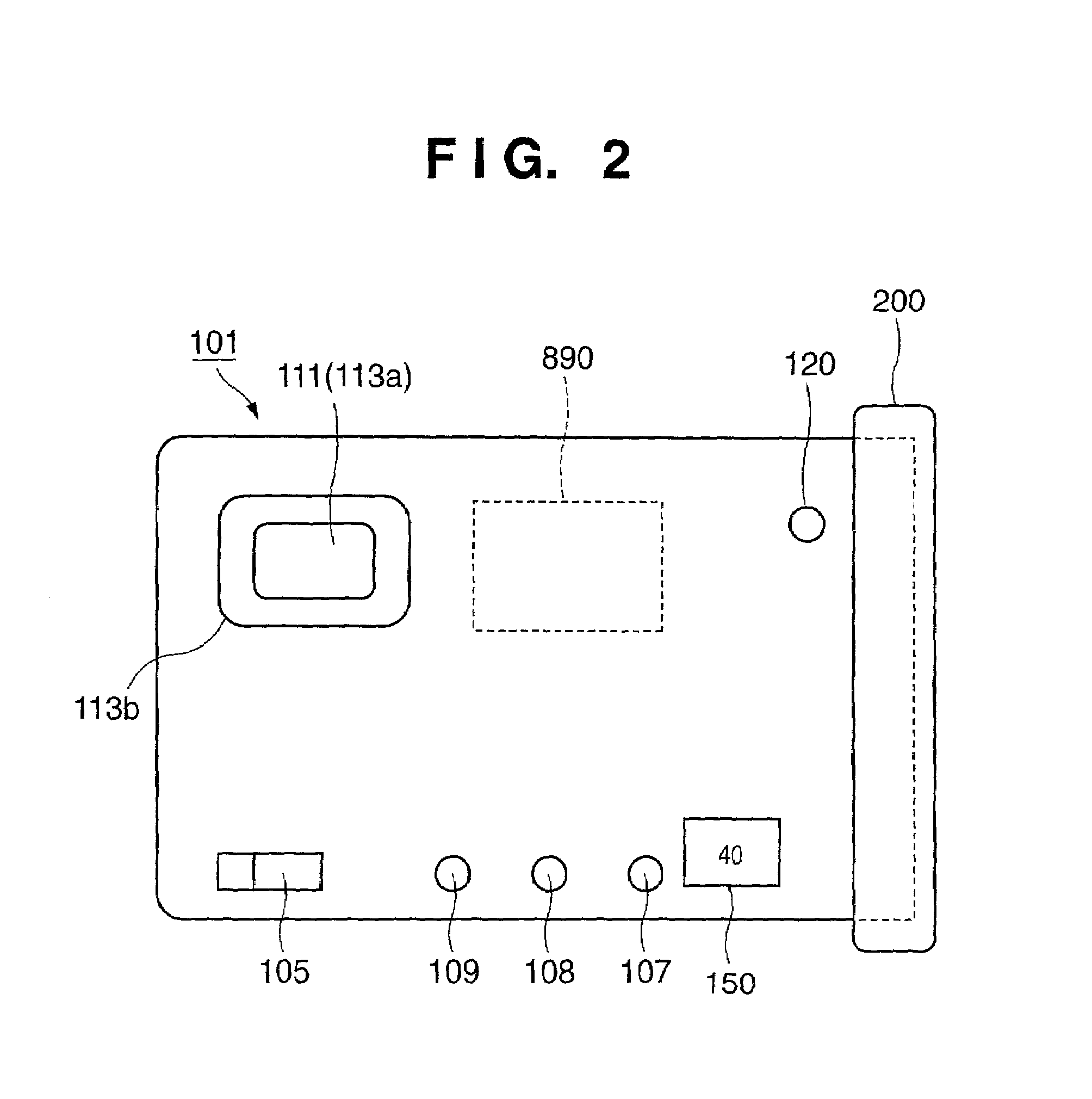
[0065]FIGS. 2, 3, and 4 show the outer appearance of a digital color camera according to the first embodiment of the present invention, in which FIG. 2 is a rear view of the camera, FIG. 3 is a side view of the camera viewed from the left side in FIG. 2, and FIG. 4 is a side view of the camera viewed from the right side in FIG. 2.

[0066]Referring to FIGS. 2, 3, and 4, reference numeral 101 denotes a card-shaped camera main body; 105, a main switch; 106, a release button (also shown in FIG. 1); 107, 108, and 109, switches with which the user sets the camera state; and 150, an indicator of the remaining photographable count. Reference numeral 111 denotes a viewfinder eyepiece window, from which object light that has entered the viewfinder exits. Reference numeral 114 denotes a standardized connection terminal which is connected to an external computer or the like to exchange data; 200, a contact protection cap which also serves as a grip; 120, a projection which is formed coaxial with ...

second embodiment

[0180]In the first embodiment, misregistration caused by changes in the image sensing system 10 (890) due to a change in temperature is corrected based on the output from the temperature sensor 165. Misregistration also occurs due to a change in object distance. The second embodiment corrects such misregistration caused by a change in object distance.

[0181]FIG. 21 shows a signal processing system which uses an output from a distance measurement device to correct misregistration. The same reference numerals denote the same components as those in the first embodiment.

[0182]As shown in FIG. 21, an image sensing apparatus has an image sensing system 10, an image processing system 20 as image processing means, a recording / reproduction system 30, and a control system 40. Furthermore, the image sensing system 10 includes a photographing lens 100, stop 110, and solid-state image sensing element 120. The image processing system 20 includes an A / D converter 500, RGB image processing circuit 4...

third embodiment

[0213]In the second embodiment, misregistration caused by a change in object distance is corrected on the basis of the output from the distance measurement device 465. In the third embodiment, such misregistration is corrected without using the output from the distance measurement device 465.

[0214]A switch 109 (FIG. 2) which is used by the user to set up the state of the camera is used as a macro photographing mode setting switch. When a near-distance object is to be photographed as the next object, the photographer presses the macro photographing mode setting switch 109. Upon detection of pressing of the macro photographing mode setting switch 109 by the operation detection circuit 430, for example, an interpolation process is done while the difference ΔS from the reference object distance St is set at −1.19 [m]. That is, ΔZS is calculated while ΔS=−1.19 in equation (22), and an interpolation process is executed based on equations (24) to (29).

[0215]With this arrangement, since no ...


PUM


Abstract

This invention has as its object to provide an image sensing apparatus which can satisfactorily correct misregistration among images, and can composite the images. To achieve this object, an image sensing apparatus includes: a plurality of apertures that receives external light from different positions; a plurality of image sensing units that outputs image signals obtained by independently receiving light that comes from an identical position of an object and is received via the plurality of apertures, and independently extracting predetermined color components for each received light; and a signal processing device that forms a signal that outputs an object image by mixing the image signals output from the plurality of image sensing units. When it is determined that a predetermined position deviation occurs between the image signals upon forming the signal that outputs the object image, the signal processing device corrects the predetermined position deviation by a signal process, and forms the signal that outputs the object image.

Description

FIELD OF THE INVENTION[0001]The present invention relates to a compact image sensing apparatus such as a digital still camera, video movie camera, and the like that adopt a solid-state image sensing element, its control method, a control program, and a storage medium.BACKGROUND OF THE INVENTION[0002]In a digital color camera, a solid-state image sensing element such as a CCD, CMOS sensor, or the like is exposed to an object image for a desired period of time in synchronism with pressing of a release button, and an image signal for one frame obtained by exposure undergoes a predetermined process such as a YC process or the like to obtain an image signal of a predetermined format. Digital image signals that represent sensed images are recorded in a semiconductor memory for respective images. The recorded image signals are solely or sequentially read out as needed to reproduce displayable or printable signals, which are output to and displayed on a monitor or the like.[0003]The present...

Claims


Application Information

Patent Timeline
Patent Type & Authority Patents(United States)
IPC IPC(8): H04N9/097H04N9/093H04N3/14H04N5/225
CPCH04N5/2254H04N9/093H01L27/14627H04N23/55H04N25/41H04N23/15H04N23/843H04N25/134
Inventor SUDA, YASUO
Owner CANON KK
Why Eureka
Try Eureka