Optical fiber distribution cabinet

a technology of optical fiber and distribution cabinet, applied in the field of optical fiber distribution cabinet, can solve the problems of not providing full and complete functionality for one or more existing cabinets, and all function less than optimally in one or more of the desired objects

Inactive Publication Date: 2007-02-08
CORNING CABLE SYST LLC
View PDF3 Cites 116 Cited by
  • Summary
  • Abstract
  • Description
  • Claims
  • Application Information

AI Technical Summary

Problems solved by technology

While existing cabinets (including the local convergence cabinet described in U.S. Pat. No. 6,792,191) satisfy most of the above objectives, all function less than optimally in one or more of the desired objects.
In particular, none of the existing cabinets ...

Method used


Image

  • Optical fiber distribution cabinet
  • Optical fiber distribution cabinet
  • Optical fiber distribution cabinet

Examples


Embodiment Construction

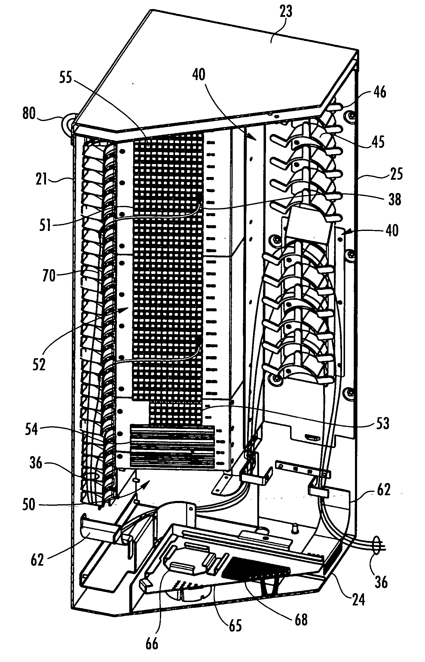
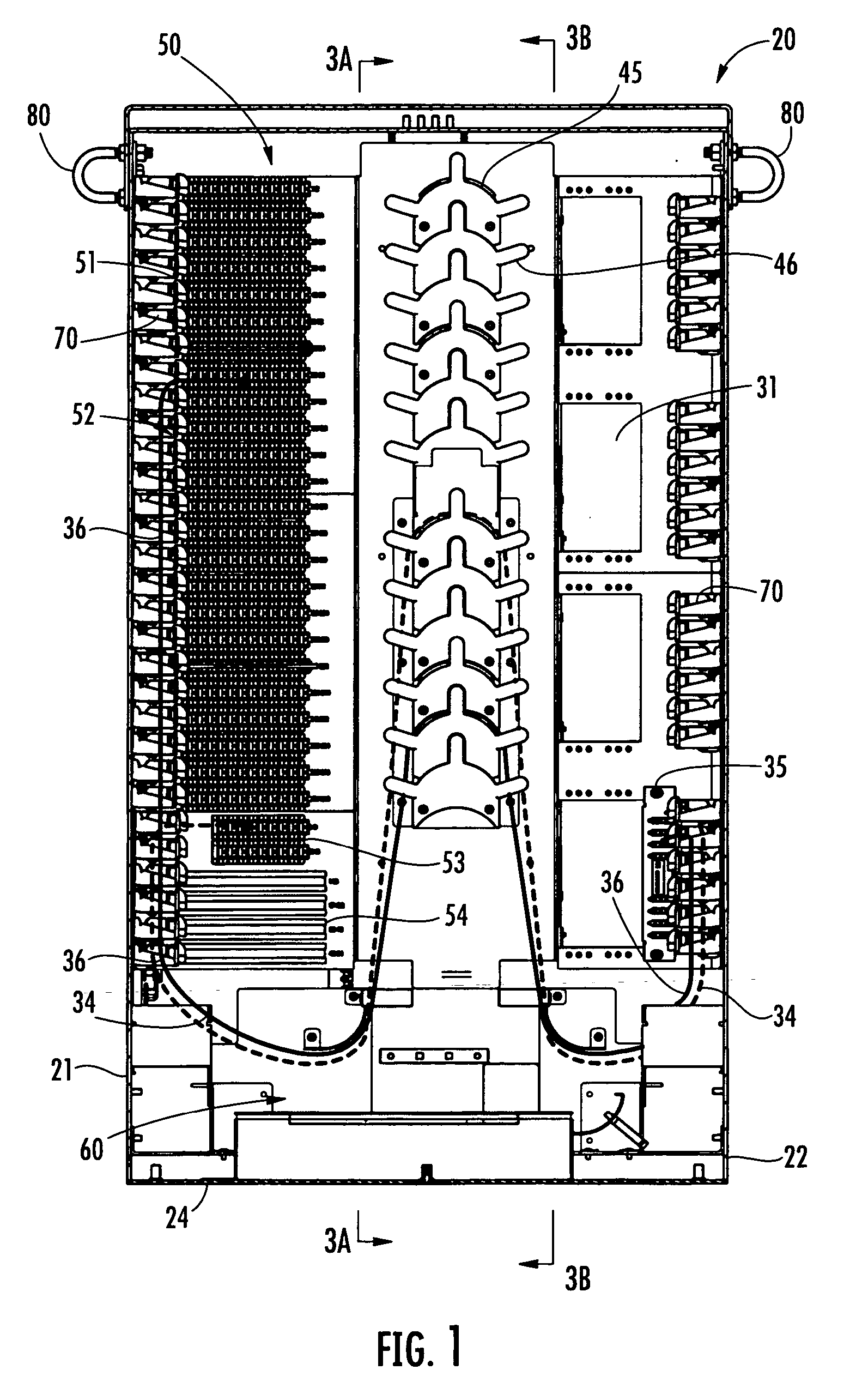
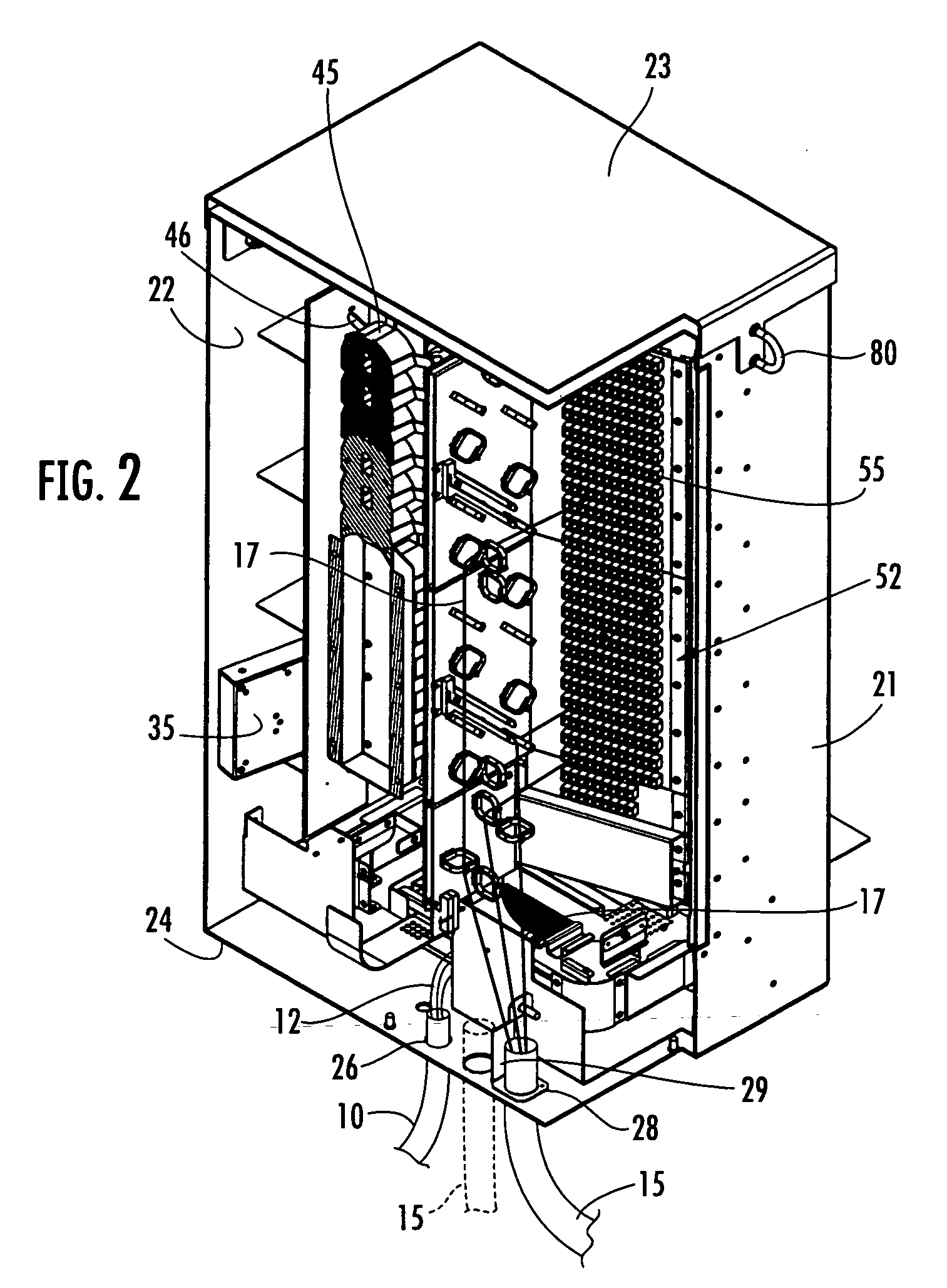
[0019] Reference will now be made in detail to exemplary and presently preferred embodiments of the invention, illustrations of which are provided in the accompanying drawings. Whenever possible, the same reference numerals are used throughout the drawings to refer to the same or similar parts. The present invention is an optical fiber distribution cabinet, sometimes referred to in the art as a fiber distribution hub (FDH) or a fiber distribution terminal (FDT), for use in the outside plant of a passive optical network (PON) as an interface between a provider of broadband optical communications services and multiple subscribers. The optical fiber distribution cabinet is operable for splitting an input optical signal carried on an optical fiber of a feeder cable into multiple output optical signals carried on corresponding optical fibers of one or more distribution cables, and for interconnecting the optical fiber of the feeder cable with the corresponding optical fibers of the distr...


PUM


Abstract

An optical fiber distribution cabinet includes at least three separate, vertically arranged areas of optical fiber functionality; namely a coupler module storage compartment, a fiber slack storage compartment, and a fiber connection compartment with the fiber slack storage compartment disposed laterally between the coupler module storage compartment and the fiber connection compartment. A plurality of pre-connectorized (pigtail or jumper) coupler module output fibers are routed from the coupler module storage compartment through the fiber slack storage compartment to the fiber connection compartment and interconnected with corresponding optical fibers of one or more pre-connectorized distribution cables. At least one coupler module input fiber is spliced directly to an optical fiber of a feeder cable. Alternatively, the coupler module input fiber is routed from the coupler module storage compartment through the fiber slack storage compartment to the fiber connection compartment and interconnected with a corresponding optical fiber of a pre-connectorized feeder cable.

Description

BACKGROUND OF THE INVENTION [0001] 1. Field of the Invention [0002] The present invention relates generally to an optical fiber distribution cabinet for use in a passive optical network (PON), and more particularly, to an optical fiber distribution cabinet for interconnecting optical fibers of a feeder cable with optical fibers of one or more distribution cables in the outside plant of a PON. [0003] 2. Technical Background [0004] It is now well known to use an optical splitter (referred to herein as a coupler module) in the outside plant of a passive optical network (PON) to distribute a broadband optical communications signal from a service provider to multiple subscribers. In a typical PON, an optical fiber distribution cabinet, sometimes referred to in the art as a fiber distribution hub (FDH) or a fiber distribution terminal (FDT), is positioned at a convenient location along a primary feeder cable to split the optical signal carried on an optical fiber of the feeder cable into ...

Claims


Application Information

Patent Timeline
IPC IPC(8): G02B6/00
CPCG02B6/4452
Inventor GARCIA, CESAR G.MITCHELL, TODD E.VARADARAJAN, HARINIGIRAUD, WILLIAM J.M.
Owner CORNING CABLE SYST LLC
Why Eureka
Try Eureka