Heat transfer tubes for evaporators

Active Publication Date: 2007-02-15
UNIV OF SHANGHAI FOR SCI & TECH +1
View PDF23 Cites 48 Cited by
  • Summary
  • Abstract
  • Description
  • Claims
  • Application Information

AI Technical Summary

Benefits of technology

[0008] It is an object of the present invention to provide a heat transfer tube for an evaporator which can significantly improve the boiling heat transfer coefficient and

Problems solved by technology

During boiling, after the vapor bubbles grow up and break away from the cavities, as it is difficult for a portion of steam retained by the cavities to be completely expelled by a liquid flowing towards the cavities due to the action of surface tension of the liquid, the cavities become new nucleation sites again.
However, in the disclosed refe

Method used


Image

  • Heat transfer tubes for evaporators
  • Heat transfer tubes for evaporators
  • Heat transfer tubes for evaporators

Examples


Embodiment Construction

[0031] Reference will now be made in detail to the present embodiments of the present invention, examples of which are illustrated in the accompanying drawings, wherein like reference numerals refer to the like elements throughout. The embodiments are described below in order to explain the present invention by referring to the figures.

[0032] However, the present application is not limited to the embodiments.

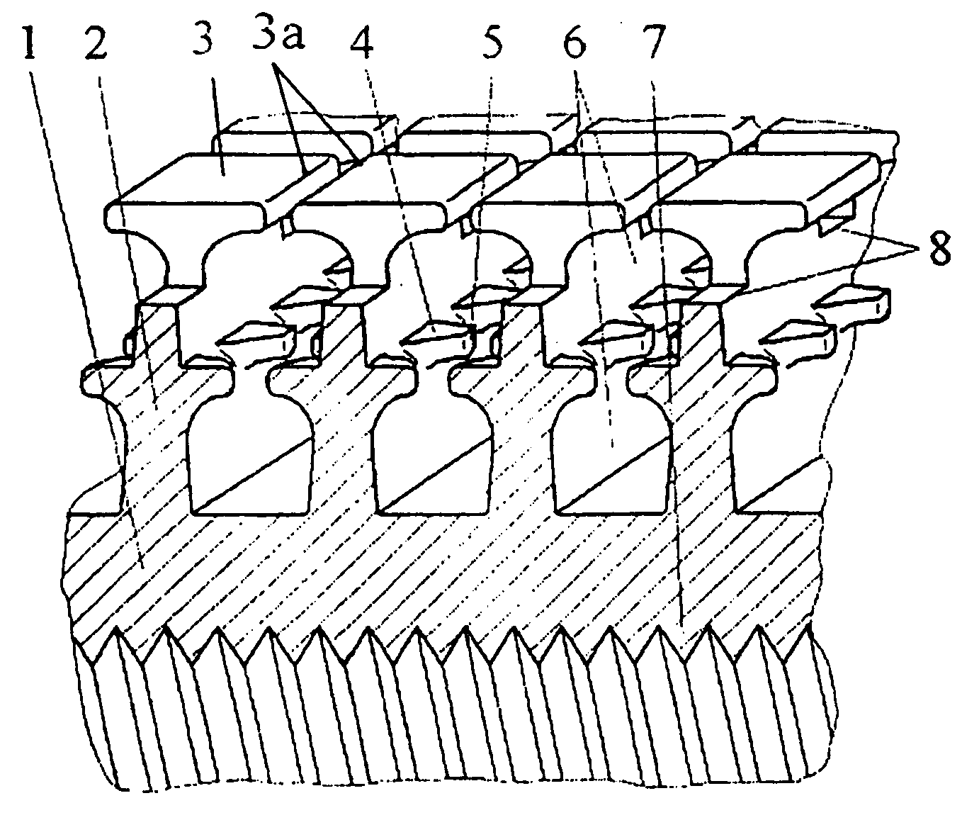
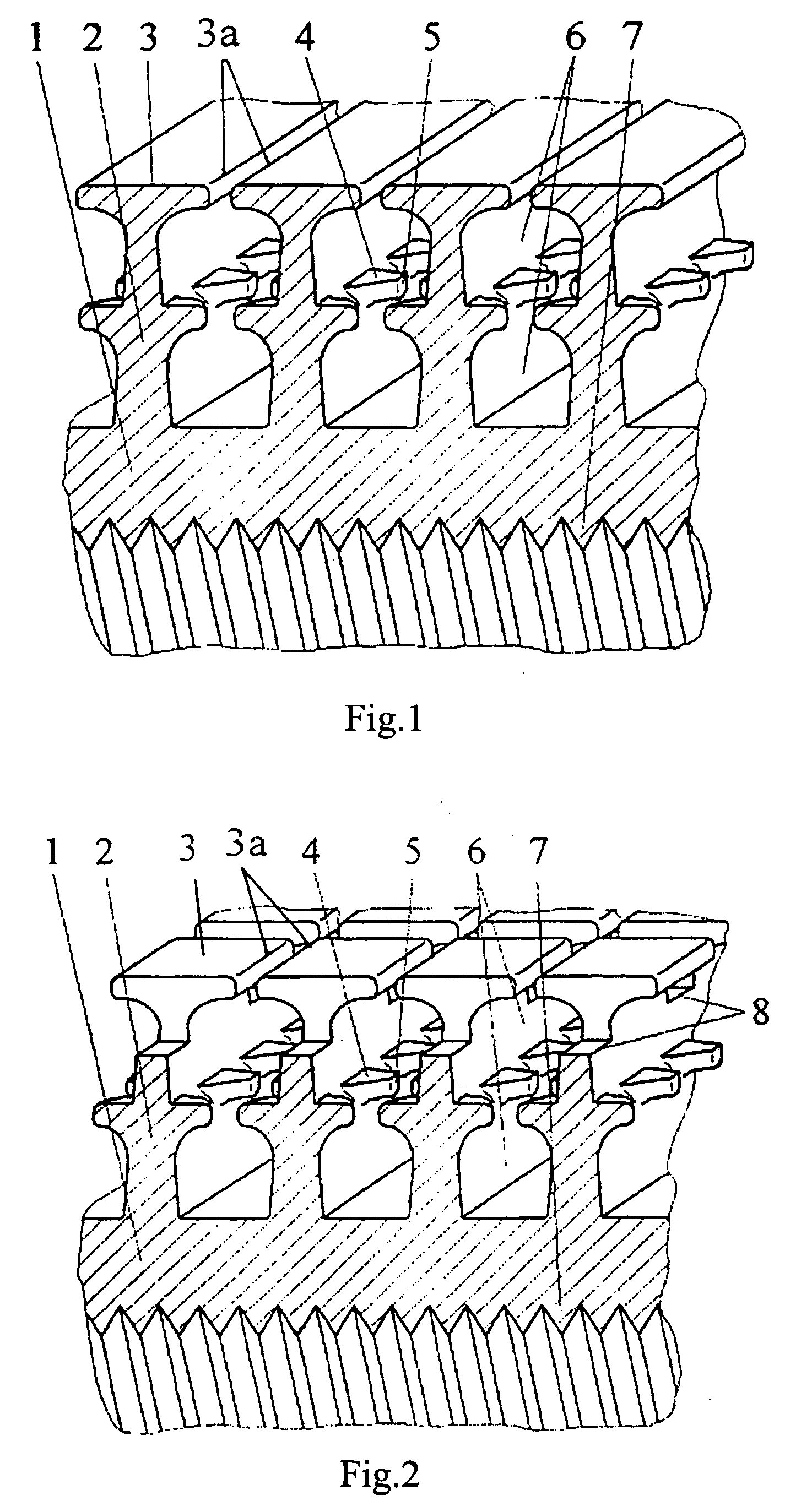
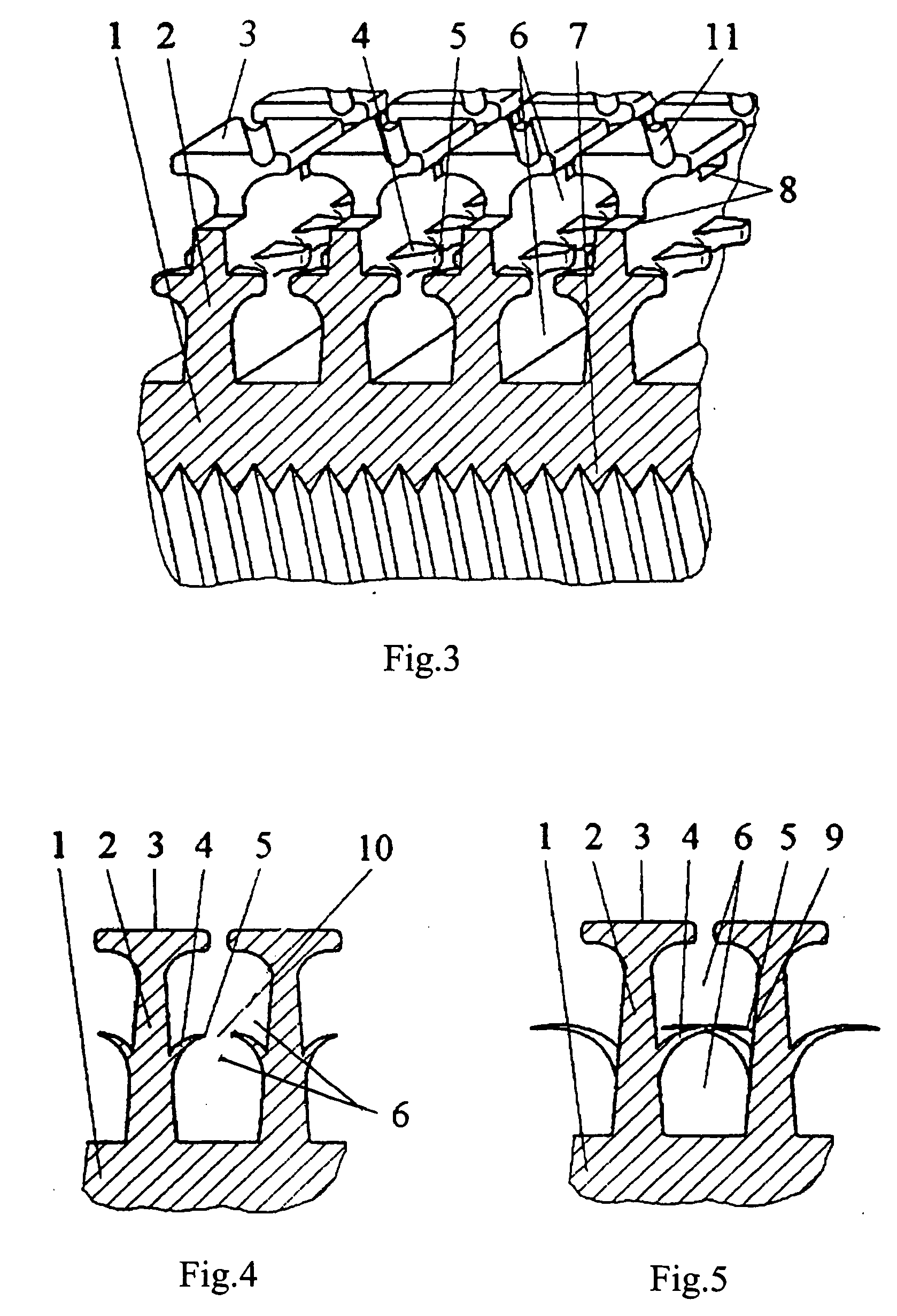
[0033] Referring to FIGS. 1 to 4, outer fins 2 may spread helically around a tube body 1, or may spread annularly around the tube body 1 so as to form a plurality of annular outer fins on the tube body 1. Alternatively, the outer fins 2 may extend in an axial direction of the tube body 1 to form a plurality of straight outer fins. Among the above three types of outer fins 2, the helical fins are preferable since it is most suitable for a heat transfer tube with helical fins to be manufactured by further providing a cutter for cutting lateral fins 4 (which will be described in ...


PUM

PropertyMeasurementUnit
Lengthaaaaaaaaaa
Lengthaaaaaaaaaa
Lengthaaaaaaaaaa

Abstract

The present invention discloses heat transfer tubes for evaporators in air conditioning and refrigeration systems, comprising: a tube body (1); outer fins (2) extending on an outer wall surface of the tube body (1) and having outer fin walls opposite to the outer fin walls of the adjacent outer fins; channels (6) located between the adjacent fins (2) so as to constitute channel chambers; fin top platforms (3) on respective tops of the outer fins (2), the fin top platforms (3) including fin top edges (3a) extending from both sides of the fin top platforms (3) so that the channel chambers take a form of a cavity structure as a whole; channel chamber openings constituted by gaps between the adjacent fin top edges (3a) of the fin top platforms (3) of the outer fins; and lateral fins (4) arranged on portions or substantially middle portions of the outer fin walls of the outer fins (2) in a height direction of the outer fins (2) and at intervals in an spreading direction of the outer fins (2), so that the cavity structure is formed into a double cavity structure. The heat transfer tube of the present application can achieve the technical effect of producing an excellent boiling heat transfer coefficient and enhancing the boiling heat transfer as well as saving material and reducing the weight of the tube body.

Description

BACKGROUND OF THE INVENTION [0001] 1. Field of the Invention [0002] The present invention relates generally to heat transfer tubes for evaporators in air conditioning and refrigeration systems, more particularly, to a heat transfer tube that has an outer wall surface formed therein with double cavity. [0003] 2. Description of the Related Art [0004] Many fields, such as refrigeration, air conditioning, process engineering, petrochemical processing, and energy source and power engineering, relate to evaporating and boiling of a liquid on an outer wall surface of a tube. Especially in evaporators used in air conditioning and refrigeration systems, a thermal resistance of boiling heat transfer in the case that a refrigerant is boiling on an outer wall surface of a tube corresponds substantially to and even larger than that of the forced convection in the tube. Therefore, it can significantly improve the heat transfer performance of the evaporator to enhance the boiling heat transfer on ...

Claims


Application Information

Patent Timeline
IPC IPC(8): F28F13/18
CPCF28D2021/0071Y10T29/49391F28F13/187F28F1/26
Inventor LU, MINGHUAZHANG, CHUNMINGCUI, XIAOYULUO, XINGMA, HUGEN
Owner UNIV OF SHANGHAI FOR SCI & TECH
Why Eureka
Try Eureka