Eureka AIR delivers breakthrough ideas for toughest innovation challenges, trusted by R&D personnel around the world.

Attachable heat radiating panel

Inactive Publication Date: 2007-02-15
CITO PRODS
View PDF41 Cites 13 Cited by
  • Summary
  • Abstract
  • Description
  • Claims
  • Application Information

AI Technical Summary

Benefits of technology

[0004] Exemplary embodiments described in the present application provide for a more even and efficient heat distribution from a radiant heating system for heating and / or cooling. The system is simple and inexpensive to install and can be installed after construction of the enclosure to be heated or cooled. A tube containing a heat transfer medium is hung below a sub-floor, above a ceiling, and / or offset from a wall. Additionally, the tube is generally hung between floor joists, ceiling joists, and / or wall studs to reduce the need for drilling holes in the joists and / or studs. Thus, the tube generally extends parallel to the floor joists, ceiling joists, and / or wall studs. A heat radiating panel is mounted to the floor joists, ceiling joists, and / or wall studs to support the tube and provide even distribution of the heating and / or cooling.

Problems solved by technology

Prior art radiant heating systems are generally difficult and time consuming to install.
Additionally, prior art radiant heating systems generally provide uneven and inefficient heat distribution.

Method used


Image

  • Attachable heat radiating panel
  • Attachable heat radiating panel
  • Attachable heat radiating panel

Examples


Embodiment Construction

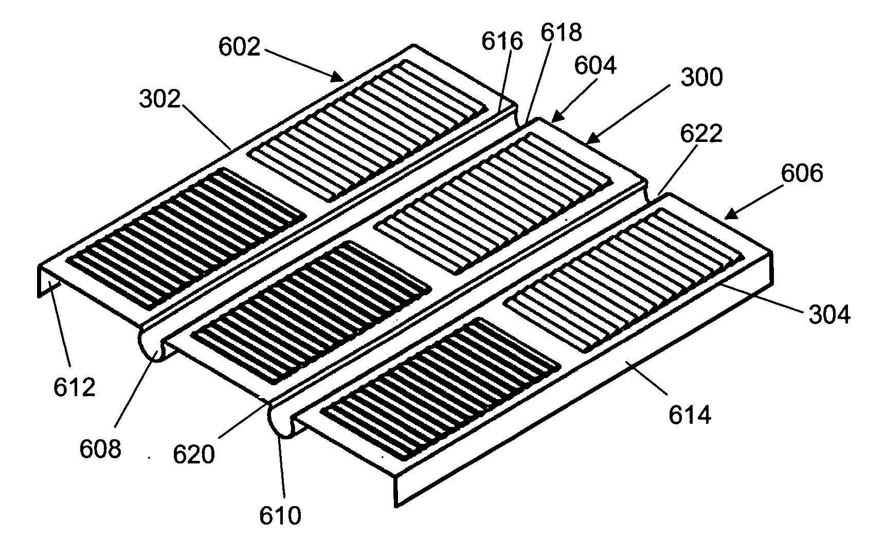
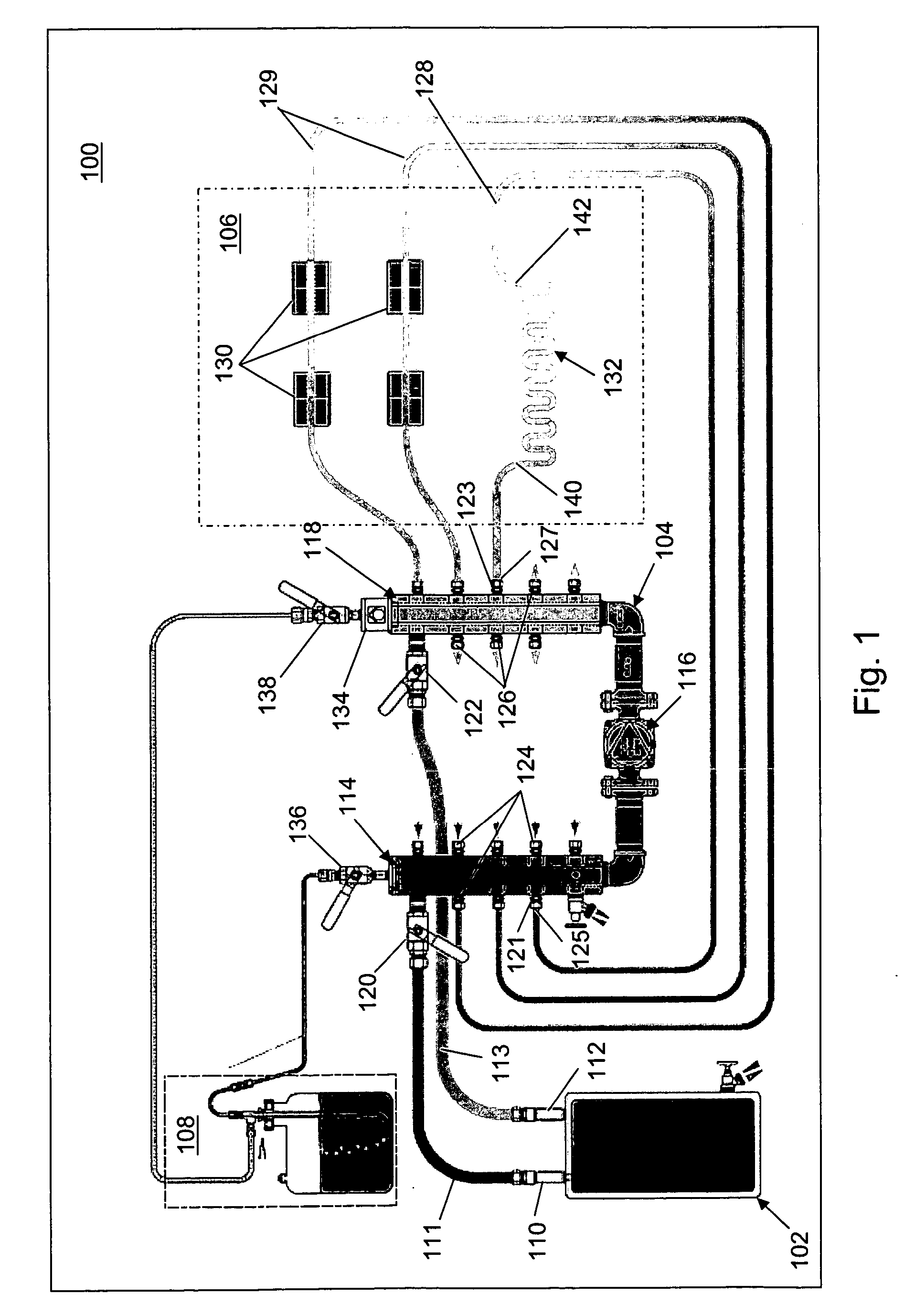
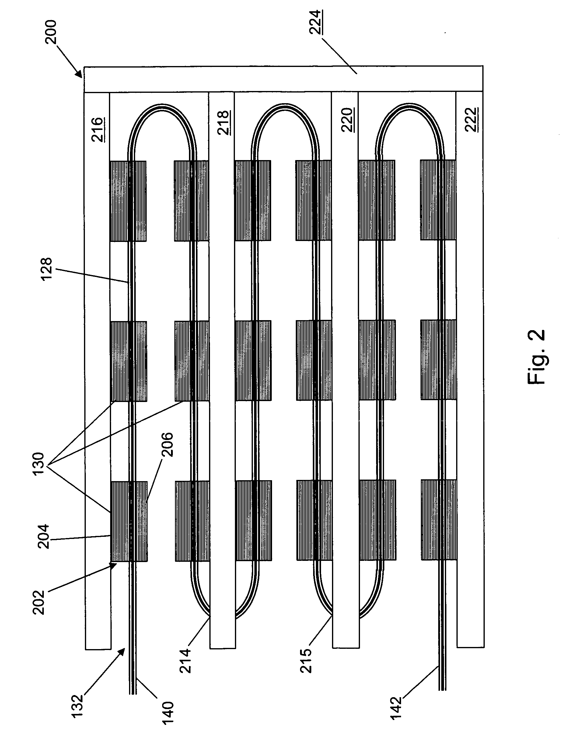
[0039] With reference to FIG. 1, a heating system 100 is shown in an exemplary embodiment. Heating system 100 may be installed in any type of structure to provide heating or cooling thereof. Heating system 100 may include a heat transfer device 102, a circulating system 104, a heat distribution system 106, and a vent assembly 108. Heating system 100 may include a fewer or a greater number of components than shown in the exemplary embodiment of FIG. 1. Heat transfer device 102 may include an outlet valve 110 and an inlet valve 112. Outlet valve 110 supplies a heat transfer medium to heat distribution system 106 through a first pipe 111 that couples to a first inlet valve 120 of a first manifold 114. Inlet valve 112 receives the heat transfer medium from heat distribution system 106 through a second pipe 113 that couples to a first outlet valve 122 of a second manifold 118. First pipe 111 and second pipe 113 may be formed of plastic, of metal, or of a combination of materials. First p...


PUM


Abstract

A radiant heating system is provided. The system includes a tube, a heat radiating panel, a fastener, and a heat transfer device. The heat radiating panel includes a heat radiating portion, and a channel extending from the heat radiating portion. The channel is sized to hold a section of the tube. The heat radiating portion may further include a plurality of slats extending from a substantially planar surface. To improve the heat distribution, the plurality of slats extend from the surface at an angle less than 90 degrees. The fastener is used to attach the heat radiating panel to the section of the tube. The heat transfer device includes an outlet valve operably coupled to supply a heat transfer medium to a first end of the tube, and an inlet valve operably coupled to receive the heat transfer medium from a second end of the tube. The heat transfer device may heat or cool the heat transfer medium.

Description

CLAIM OF PRIORITY [0001] This application is a continuation-in-part of U.S. patent application Ser. No. 11 / 161,708, filed Aug. 12, 2005, the disclosure of which is incorporated herein by reference in its entirety.FIELD OF THE INVENTION [0002] The present application relates generally to a heat radiating panel utilized in a radiant heating system. More specifically, the present application relates to a heat radiating panel that is attachable to heat transfer tubing and to a floor joist, wall stud, or ceiling joist. BACKGROUND OF THE INVENTION [0003] Various radiant heating systems have been developed for installation in walls, floors, and / or ceilings. The radiant heating systems can be mounted to and / or formed in diverse building materials. Of the various types of radiant heating systems, one of the more popular types utilizes a heat transfer medium such as water which is pumped through a closed-loop piping system. Typically, the closed loop piping is mounted in close contact with a ...

Claims


Application Information

Patent Timeline
IPC IPC(8): F28F1/32
CPCF24D3/14F28D1/0477F24D3/148F28F1/22F28F1/20Y02B30/00
Inventor WIEDER, HORST K.
Owner CITO PRODS
Why Eureka
Eureka Blog
Learn More