Remote vehicle safety device

Inactive Publication Date: 2007-02-15
GABRIELE JOHN
View PDF12 Cites 26 Cited by
  • Summary
  • Abstract
  • Description
  • Claims
  • Application Information

AI Technical Summary

Benefits of technology

[0023] It is another object of the present invention to provide a system for remotely stopping a child's vehicle to prevent injury

Problems solved by technology

With the advent of new battery technology and high efficiency electric motors, these vehicles may outpace a running parent.
Since the children riding these vehicles do not have a great appreciation for danger, it is possible that they may wander into the path of an oncoming car or drive off an e

Method used


Image

  • Remote vehicle safety device
  • Remote vehicle safety device
  • Remote vehicle safety device

Examples


Example

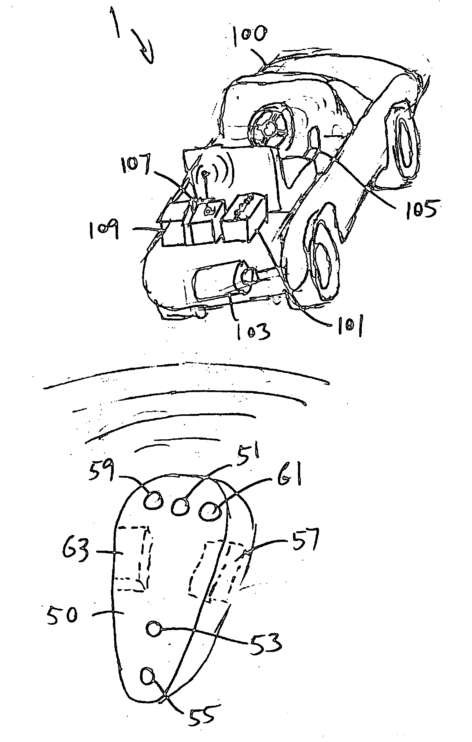
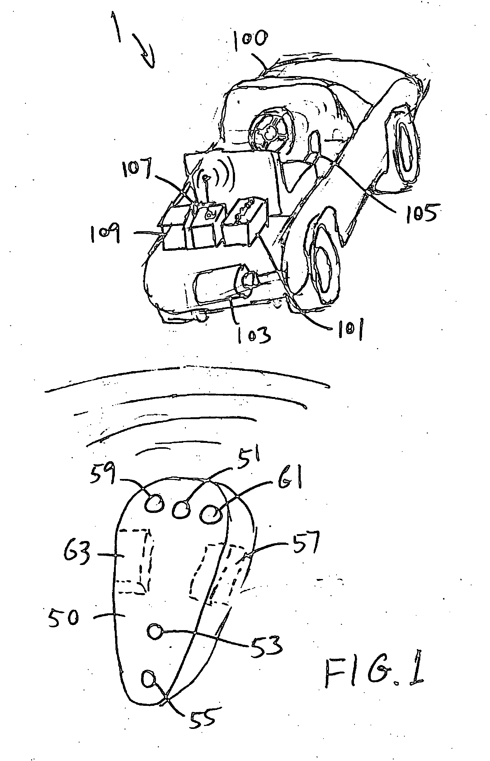
[0029]FIG. 1 is a perspective view of one embodiment of the remote vehicle safety device 1 according to the present invention. A vehicle 100, intended to be ridden by a child or adolescent, is shown. Vehicle 100 is the type which is designed for a child to sit on and operate the pedals to drive the vehicle 100. Vehicle 100 includes a self-contained battery 101 powering an electric motor 103. Battery 101 is typically a deep cycle, high-energy rechargeable battery.

[0030] Vehicle 100 includes a switch (accelerator pedal) 105 which is a switch completing a circuit between battery 101 and motor 103. Pedal 105 may also be a variable resistor or current splitter, causing some degree of current to flow to motor 103, thereby allowing variable acceleration from a standing stop.

[0031] As a child riding vehicle 100 begins to stray away or begins to approach a dangerous location, a user, which is typically a parent or guardian, presses a button 51 on a remote control 50. This activates a remot...


PUM


Abstract

A remote vehicle safety system for use with a child-operated riding vehicle (100) employs a portable remote control (50) operated by a user, having a transmitter (57) for transmitting a signal to a receiver (107) on the vehicle (100). The receiver recognizes the signal from the transmitter (57). The receiver (107) then operates an actuator (211) causing a modification circuit (109) to modify power being provided to a motor (103) on vehicle (100). It may slow or stop the vehicle (100) preventing a child rider from getting into a dangerous situation.

Description

CROSS REFERENCE TO RELATED APPLICATIONS [0001] This patent application claims priority from US. Provisional Patent Application 60 / 707,130 filed Aug. 9, 2005. BACKGROUND OF THE INVENTION [0002] 1. Field of the Invention [0003] The present invention relates to a safety device which controls riding vehicles from a remote location. [0004] 2. Discussion of Related Art [0005] Riding vehicles, such as electric toy cars and motorized scooters intended to be used by children and adolescents are rapidly advancing in technology. With the advent of new battery technology and high efficiency electric motors, these vehicles may outpace a running parent. Since the children riding these vehicles do not have a great appreciation for danger, it is possible that they may wander into the path of an oncoming car or drive off an embankment. [0006] There have been attempts to provide safety devices to protect children against these dangers and similar problems. For example, U.S. Pat. No. 4,785,291 describ...

Claims


Application Information

Patent Timeline
IPC IPC(8): B60T7/16
CPCA63H30/04B60T7/16B62K2204/00B62K9/00B62J27/00B60L2200/20
Inventor GABRIELE, JOHN
Owner GABRIELE JOHN
Why Eureka
Try Eureka