
Self-locking grate for deck drain fitting

a self-locking, drain fitting technology, applied in sewer cleaning, filtration separation, separation processes, etc., can solve the problems of falling into the drain, one or more screws can easily be lost by rolling away, and inconvenient to handle multiple screws

Inactive Publication Date: 2007-02-15
BESTWELD
View PDF57 Cites 37 Cited by
  • Summary
  • Abstract
  • Description
  • Claims
  • Application Information

AI Technical Summary

Benefits of technology

[0008] The present invention, in one aspect, comprises a self-locking grate for a drain fitting, the grate eliminating the need for screws for attaching the grate to the drain fitting.
[0016] The invention has the further object of reducing the cost of maintenance of drains, by eliminating the need for screws in attaching a grate to a drain fitting.
[0017] The invention has the further object of simplifying the procedure for attaching and removing a grate from a drain, which is especially valuable when the marine vehicle is moving in a seaway.
[0018] The invention has the further object of reducing the cost of maintaining deck and platform drain systems, especially on a marine vessel.

Problems solved by technology

The above design has several disadvantages, especially when maintaining the drain fitting while the marine vehicle is in a seaway.
First, it is inconvenient to handle multiple screws while removing and reattaching the grate.
One or more screws can easily become lost by rolling away, or they can even fall into the drain.
Secondly, a more serious problem arises when the grate has been removed and reattached many times. After many iterations, the drain fitting body threads for the screws are likely to become worn, and they eventually may become stripped.
This is an operation that usually cannot be either conveniently or safely performed while at sea.
If the subject deck or platform is also the surface of a tank, the replacement of a deck drain fitting is especially costly.

Method used


Image

  • Self-locking grate for deck drain fitting
  • Self-locking grate for deck drain fitting
  • Self-locking grate for deck drain fitting

Examples


Embodiment Construction

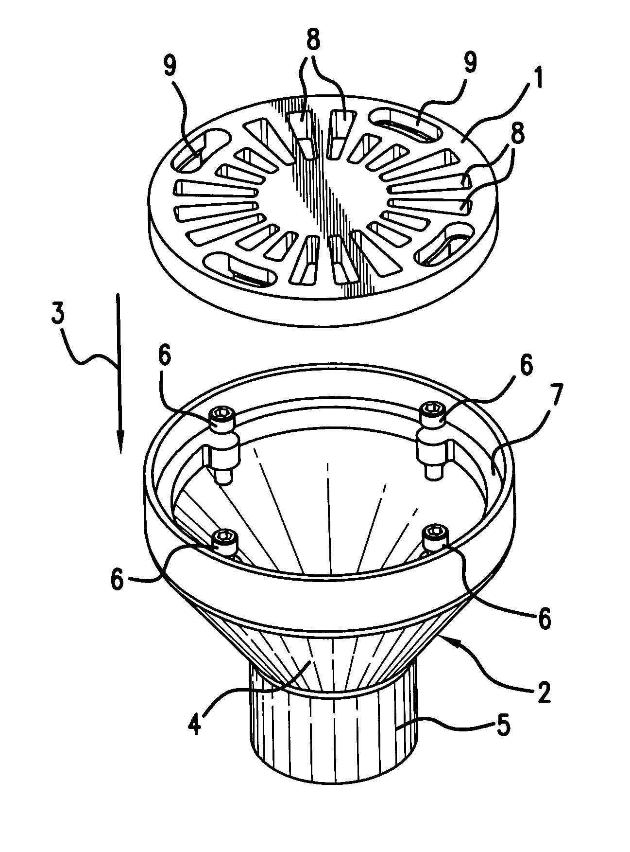
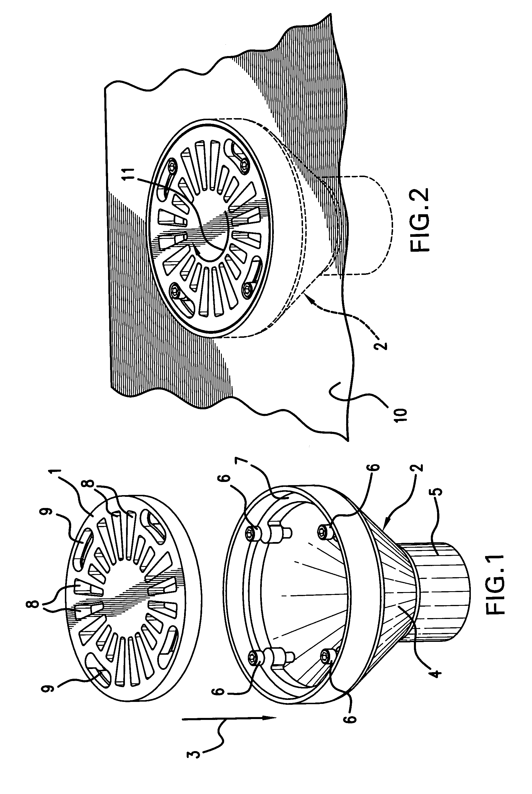
[0031] The present invention comprises a self-locking grate for a drain fitting. The basic structure of the invention is shown in the exploded perspective view of FIG. 1. Grate 1 comprises a cover for drain fitting body 2, the grate being placed over the drain fitting body as indicated by arrow 3. The drain fitting body includes a flared, generally conical terminus 4, which connects to a drain pipe 5. The drain fitting body includes a plurality of studs 6, the studs being permanently mounted to the interior of the flared terminus 4, as shown. A flange 7 provides a seat for the grate. Each stud defines a stud head, as shown.

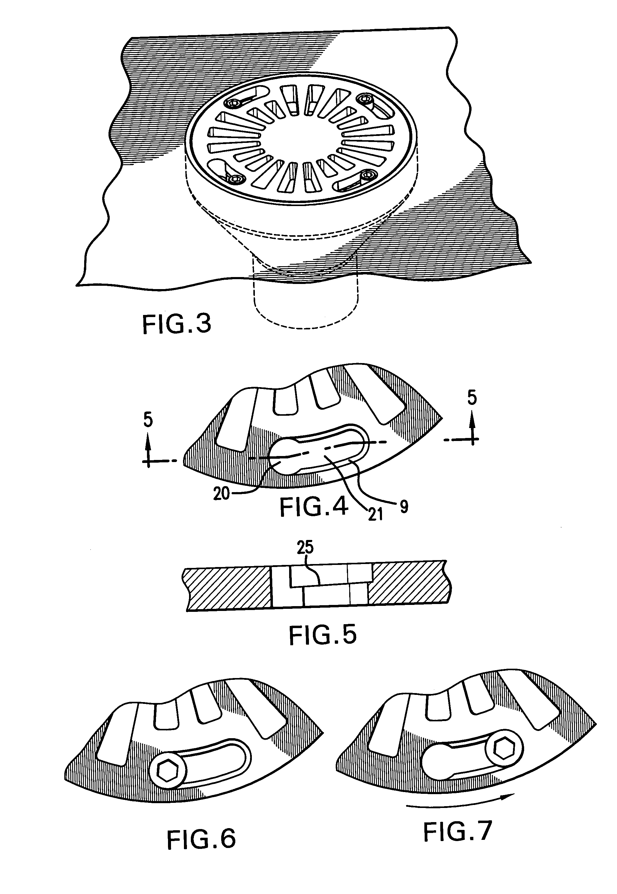
[0032] The grate includes a plurality of strainer holes, such as those designated by reference numeral 8, the strainer holes comprising means for preventing relatively large debris from falling into the drain. The grate also includes arcuate elongated openings 9, each elongated opening having a portion that is of enlarged diameter relative to that of the remainde...


PUM

PropertyMeasurementUnit
Forceaaaaaaaaaa
Diameteraaaaaaaaaa
Shapeaaaaaaaaaa

Abstract

A self-locking grate for a drain fitting body includes a plate having strainer holes and arcuate elongated openings near the periphery of the grate. Enlarged diameter portions of the elongated openings fit over studs connected to a drain, and the grate can be rotated to engage the studs, so that the grate is wedged to the drain fitting body without the use of screws. An inclined ledge, formed in the elongated openings, acts as a cam surface to wedge against the grate as it is rotated into the locked position. Despite the absence of screws, the grate is unlikely to loosen due to vibration or shock. A tool capable of simultaneously engaging distinct holes in the grate can be used to rotate the grate between the locked and unlocked positions. The invention also includes a kit for converting a conventional drain fitting and grate into a drain fitting and grate of the present invention.

Description

BACKGROUND OF THE INVENTION [0001] The present invention relates to floor drain and deck drain fittings, especially deck drain fittings used in marine applications, including ships, boats, barges, and other vehicles and structures such as drilling platforms. The invention provides a method and apparatus for easily removing and replacing a grate for a drain fitting, for the purposes of inspecting a drain body, clearing an obstruction, and / or cleaning and repairing any of the parts thereof. [0002] It is known to provide drain pipes on ships, for removing water that may accumulate on a deck or platform. Such drain pipes typically terminate in a flared, generally conical structure, or drain fitting, which is capped with a grate. The grate prevents relatively large pieces of debris from falling into the drain fitting and causing clogs, while allowing water, and solid material having a relatively small size, to flow into the drain. The grate and drain structures are usually arranged so th...

Claims


Application Information

Patent Timeline
IPC IPC(8): E03F5/06
CPCE03F2005/063E03F5/06Y02A30/60
Inventor BAYARD, RODOSCAR, WILLIAMCOMMO, CHARLES R.OAKES, FULTON D. JR.
Owner BESTWELD
Features
  • Generate Ideas
  • Intellectual Property
  • Life Sciences
  • Materials
  • Tech Scout
  • Unparalleled Data Quality
  • Higher Quality Content
  • 60% Fewer Hallucinations
Learn More