Tele-diagnostic device

a tele-diagnostic device and tele-diagnostic technology, applied in the field of probes, can solve the problems of curtailing the need for more frequent personal visits, and achieve the effects of convenient use, convenient portability, and low cos

Inactive Publication Date: 2007-02-15
INEEDMD COM
View PDF43 Cites 11 Cited by
  • Summary
  • Abstract
  • Description
  • Claims
  • Application Information

AI Technical Summary

Benefits of technology

[0008] An object of the present invention is to provide an inexpensive, simple to use, and portable probe, and a system and method for use with the probe, that could gather a plurality of diagnostic / monitoring information, including a 10 leadwire EKG.

Problems solved by technology

These innovations have curtailed the need for more frequent personal visits, by the patient or the doctor, as the case may be.

Method used


Image

  • Tele-diagnostic device
  • Tele-diagnostic device
  • Tele-diagnostic device

Examples


Embodiment Construction

[0014] The present invention relates to a diagnostic / monitoring probe, and a system and method for use with the probe, for obtaining medical diagnostic information. In particular, the present invention relates to a probe, and a system and method for use with the probe, for obtaining cardiac related diagnostic and monitoring information.

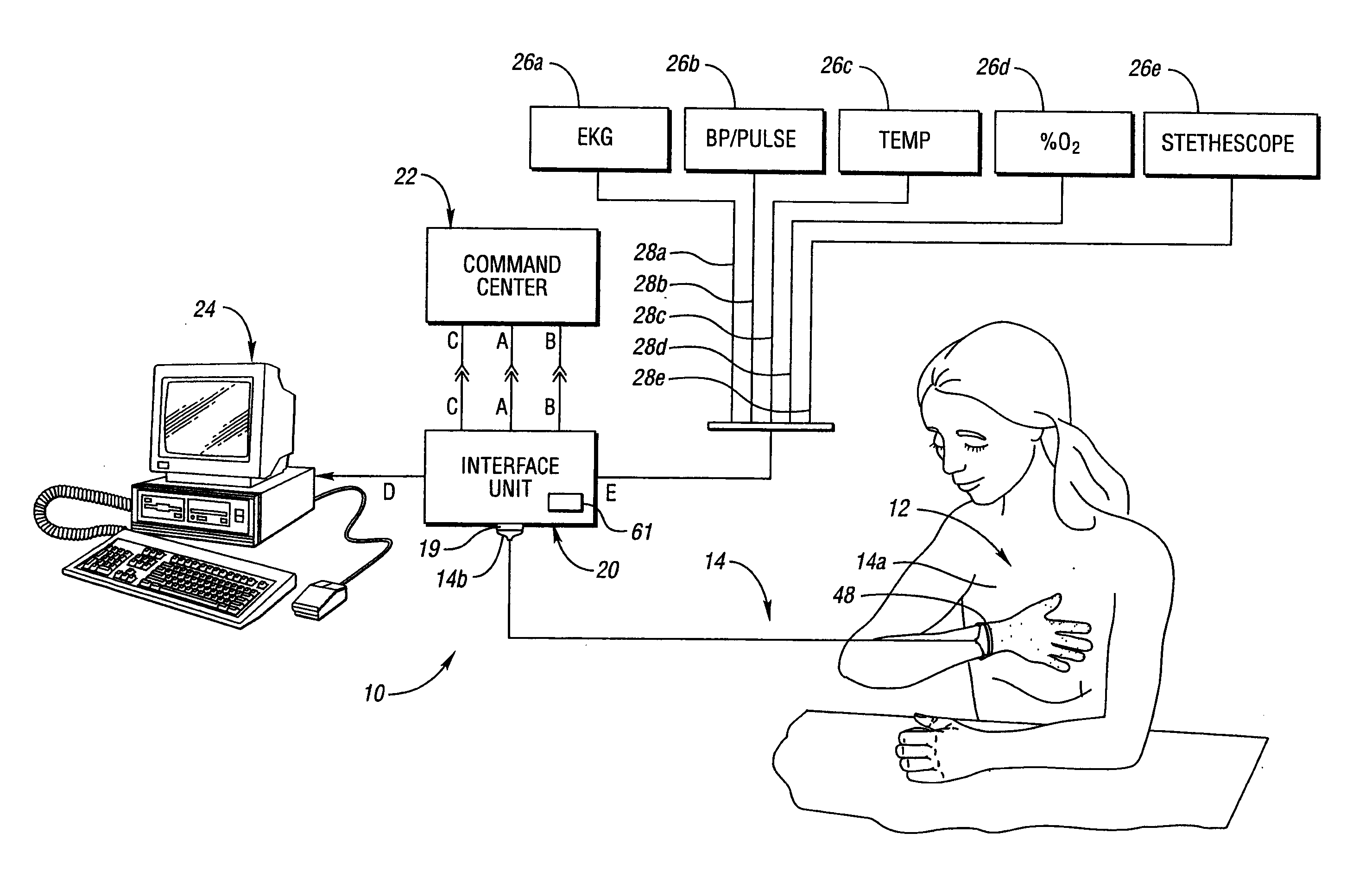
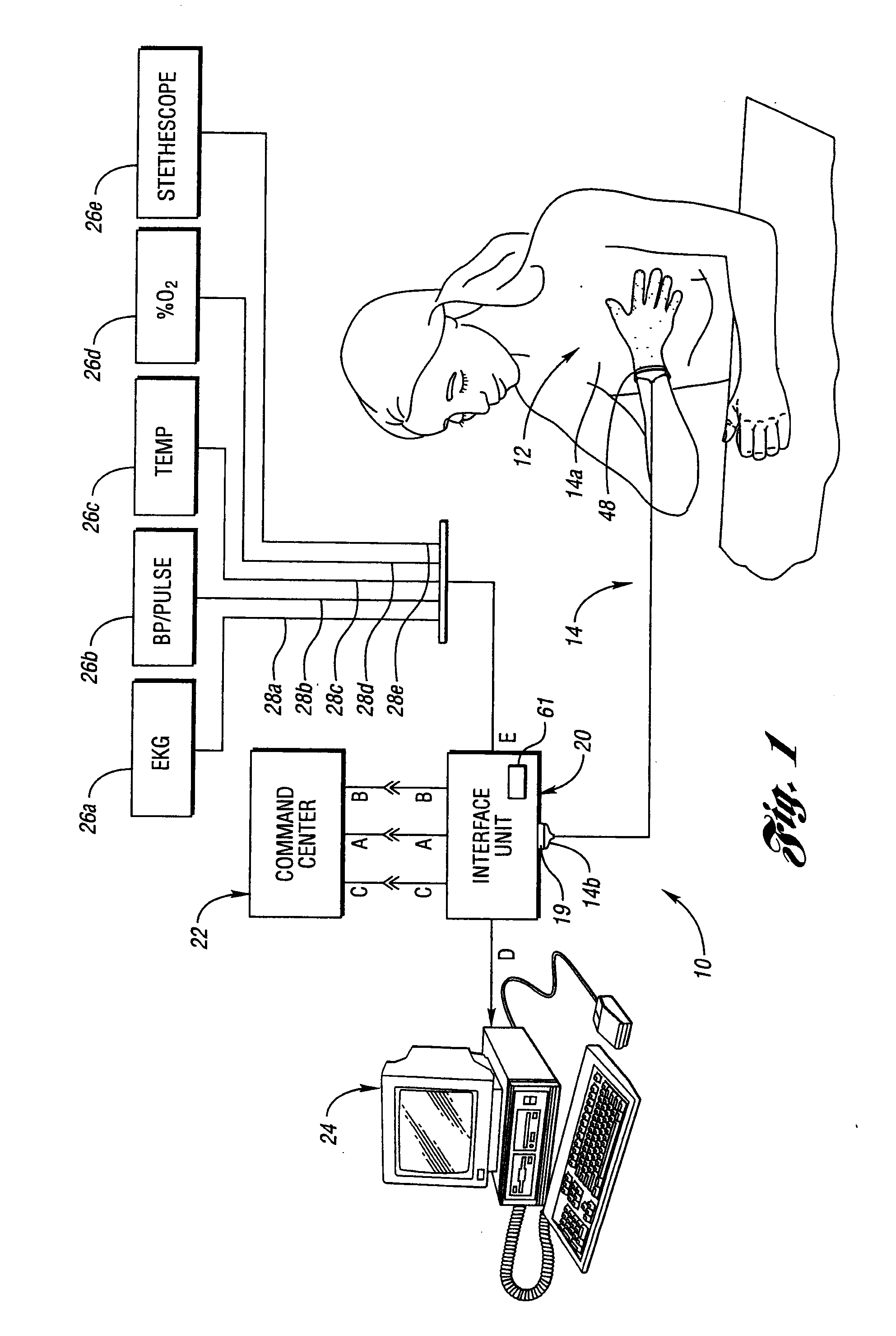
[0015] As representative of the present invention, FIG. 1 illustrates a system 10 for obtaining diagnostic information. The system 10 includes a glove probe 12. The glove probe 12 is a unitary member which is adaptable to be worn over a person's hand. The glove probe 12 includes a plurality of medical diagnostic probes which detect diagnostic signals, as will be explained in more detail below. The glove probe 12 is preferably connected via a cable 14 to an interface unit 20 and, thus communicates with, and is capable of transmitting diagnostic signals, or information, from the medical diagnostic probes to the interface unit. The glove 12 could altern...


PUM


Abstract

A system, probe, and method for collecting a plurality of diagnostic information and transmitting the diagnostic information to a remote location. The system comprises a member contoured to at least a portion of a person's hand, and an interface unit in electrical communication with the member. The interface unit is capable of transmitting information to a remote location. The member comprises at least eight sensors.

Description

CROSS-REFERENCE TO RELATED APPLICATIONS [0001] This application is a continuation of U.S. application Ser. No. 10 / 024,105, filed Dec. 18, 2001 (pending) which is a continuation-in-part of U.S. patent application Ser. No. 09 / 884,371, filed Jun. 19, 2001, and Ser. No. 09 / 741,283, filed Dec. 19, 2000. U.S. patent application Ser. No. 09 / 884,371 is a continuation of U.S. patent application Ser. No. 09 / 188,971, filed Nov. 10, 1998, now U.S. Pat. No. 6,248,064, issued on Jun. 19, 2001, which is a continuation-in-part of U.S. patent application Ser. No. 09 / 084,647, filed May 26, 1998, now U.S. Pat. No. 6,224,548, issued on May 1, 2001. U.S. patent application Ser. No. 09 / 741,283 is a continuation of U.S. patent application Ser. No. 09 / 084,647, filed May 26, 1998, now U.S. Pat. No. 6,224,548, issued May 1, 2001. Each of the above-identified applications are incorporated herein by reference.BACKGROUND OF THE INVENTION [0002] 1. Field of the Invention [0003] This invention relates to a probe,...

Claims


Application Information

Patent Timeline
Patent Type & Authority Applications(United States)
IPC IPC(8): A61B5/02A61B5/00A61B5/0205A61B5/022A61B5/024A61B5/0408A61B7/00
CPCA61B5/0002A61B5/02055A61B5/021A61B5/022A61B5/024A61B5/02438A61B2562/168A61B5/04085A61B5/1455A61B5/14552A61B5/6806A61B7/003A61B7/04A61B5/0404A61B5/282A61B5/332
Inventor GOPINATHAN, GOVINDANTILFORD, ARTHUR R.
Owner INEEDMD COM
Why Eureka
Try Eureka