Device for Controlling a Rotating Electrical Machine

a technology for electrical machines and control devices, applied in the direction of electronic commutators, dynamo-electric machines, synchronous motor starters, etc., can solve the problems of complex implementation of resolvers, high equipment costs, and inability to meet the needs of users, and achieve the effect of less expensiv

Active Publication Date: 2008-12-18
VALEO EQUIP ELECTRIC MOTEUR
View PDF7 Cites 5 Cited by
  • Summary
  • Abstract
  • Description
  • Claims
  • Application Information

AI Technical Summary

Benefits of technology

[0024]It is found that, in each case, the device according to the invention does not involve any expensive equipment since in the first case the magnetic field is directly supplied by the rotor itself and in the second case the magnetic field is supplied by a target, since a direct calculation is made of the position of the rotor with respect to a magnetic field of the rotor or of the target, the latter being less expensive than a resolver.

Problems solved by technology

However, this type of equipment has a certain number of drawbacks.
Resolvers are in fact expensive and their implementation to make them operational is complex because of the coupling to be effected between such a resolver and the machine itself requiring the presence of electronic computing components to supply a correct position of the rotor of the machine from the coupling parameters.
In addition, they are sensitive to the magnetic disturbance caused by the stray magnetic field produced by the rotor, which causes a malfunctioning of the system and therefore measurement errors and poor control of the machine.
In addition, the mechanical strength of this device is not perfect since it is particularly sensitive to the vibration of the machine because of the mounting on the end of the rotor shaft.
Finally, their resistance to salt spray and dust is not completely satisfactory.

Method used


Image

  • Device for Controlling a Rotating Electrical Machine
  • Device for Controlling a Rotating Electrical Machine
  • Device for Controlling a Rotating Electrical Machine

Examples


first embodiment

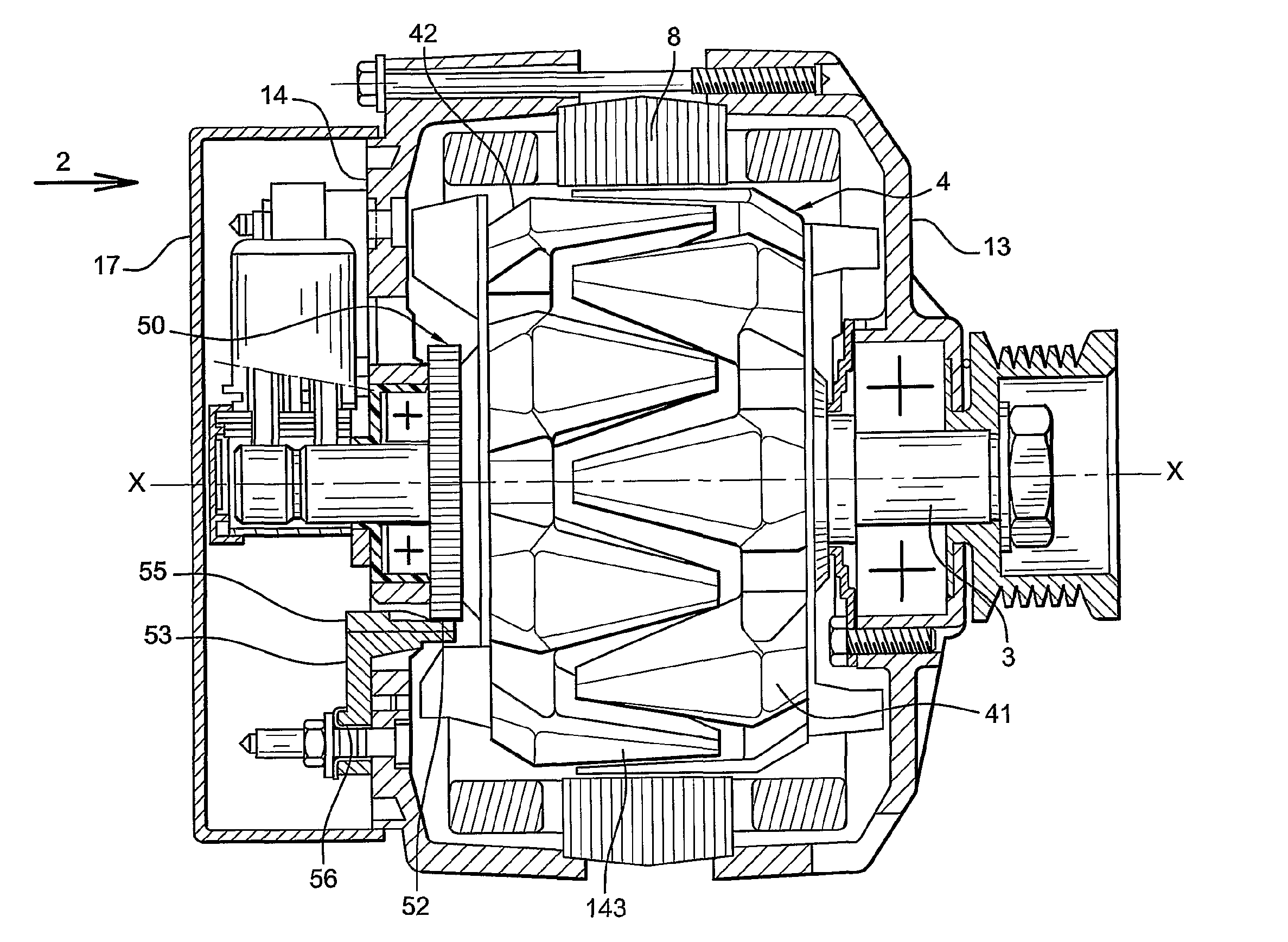
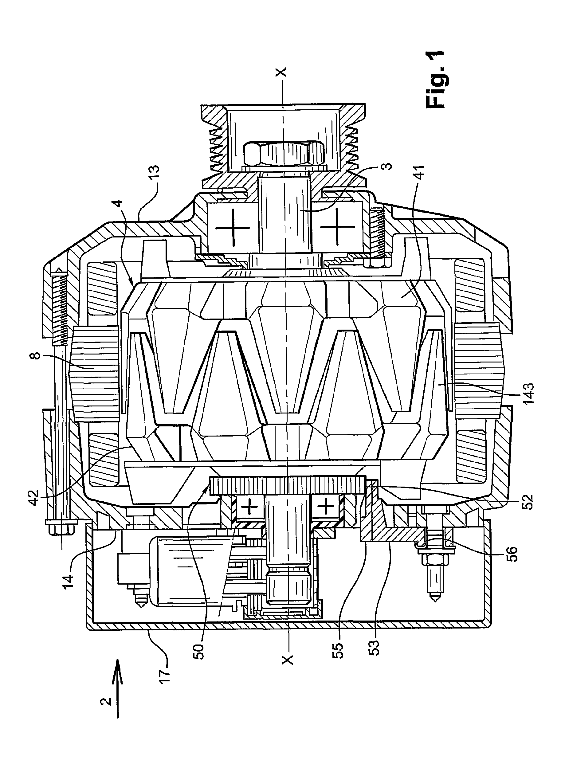
[0034]FIG. 1 depicts such a rotary electrical machine comprising, in a [0035]a wound stator 8 provided here with three windings for defining three phases 10 (depicted FIG. 2), the stator also comprising poles,[0036]a rotor 4 comprising two magnet wheels with claws 41, 42 fixed to a shaft 3, the claws also being referred to as teeth 143. The teeth of one of the magnet wheels are interlocked with one another. When the rotor is supplied with current, the teeth on one of the magnet wheels define North poles, whilst the teeth on the other magnet wheel define South poles. The rotor is thus magnetised. There is then a creation of pairs of North-South poles,[0037]a front 13 and rear 14 bearing to which a protective cover 17 is fixed, the said bearings allowing rotary mounting of the respective front and rear ends of the shaft 3 of the rotor,[0038]a device for determining the position θ(t) of the rotor 4, and[0039]an axial or radial reading target 50 rotationally fixed to the rotor, or parti...

second embodiment

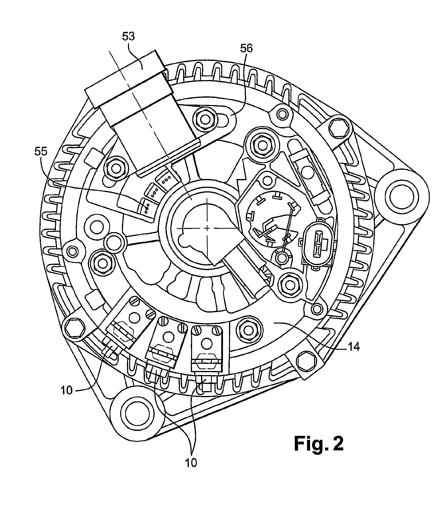
[0049] the magnet field sensors 52 are located facing the rotor 4 and the sensor holder 53 is fixed to the face of the front bearing 13.

[0050]In a first variant embodiment, the sensors 52 are located radially on the side of the rotor 50, perpendicular with respect to the shaft 3 of the rotor 4 so that the reading is radial.

[0051]In a second variant embodiment, the sensors 52 are located axially on the top of the rotor 4, in the axis of the shaft 3 of the rotor 4, so that the reading is axial.

[0052]Preferentially, the sensors are moulded onto the sensor holder 53, the latter preferably being made from plastics material. This enables the assembly consisting of sensor and sensor holder to be impervious and thus to be less sensitive to salt spray and dust.

[0053]FIG. 3 shows an example of an embodiment of a sensor holder 53 for radial reading. The said sensor holder 53 comprises in particular:[0054]a connector 257 in which metal tracks make a connection between the said connector and the...


PUM


Abstract

A device for determining the position of the rotor of a rotating electrical machine. The invention is characterized in that the device comprises a plurality of magnetic field sensors stationary relative to the stator and adapted to deliver multiphase electric signals representing a magnetic field detected by the sensors, and means for processing the multiphase electric signals by an operator capable of providing diphase signals depending on the position of the rotor. The invention is applicable to rotating electrical machines used in the automotive industry.

Description

FIELD OF THE INVENTION[0001]The present invention concerns a device for determining the position of the rotor of a rotary electrical machine comprising a stator.[0002]The invention finds a particularly advantageous application in the field of reversible machines, or alternator / starters, used in the automotive industry, both in alternator mode and in motor mode on starting up or as an assistance to takeoff (boosting) as from 500 revolutions / minute.PRIOR ART[0003]A reversible machine comprises an alternator including:[0004]a rotor comprising a field winding associated conventionally with two collecting rings and two brushes by means of which an excitation current is brought;[0005]a multiphase stator carrying several coils or windings that are connected in star or delta in the most frequent case of a three-phase structure and that deliver to a bridge rectifier, in alternator functioning, a converted electric power. The machine has two bearings, front and rear, for fixing it to the ther...

Claims


Application Information

Patent Timeline
Patent Type & Authority Applications(United States)
IPC IPC(8): H02P21/00
CPCG01D5/24409G01D5/2451H02K29/08G01P3/487H02K29/06H02P6/16
Inventor CHEMIN, MICHAELLEROUX, FREDERICKONAN, GILBERT
Owner VALEO EQUIP ELECTRIC MOTEUR
Why Eureka
Try Eureka