Rotary die device

a rotary die and die technology, applied in the direction of saw chains, sawing equipment, metal working equipment, etc., can solve the problems of reducing cutting force, looseness between the two units, and difficulty in aligning the axes of both units with each other, and achieve the effect of smooth adjustment of the movable uni

Inactive Publication Date: 2007-02-22
MITSUBISHI MATERIALS CORP
View PDF13 Cites 7 Cited by
  • Summary
  • Abstract
  • Description
  • Claims
  • Application Information

AI Technical Summary

Benefits of technology

[0009] The invention has been made to solve the above-mentioned problems, and it is an object of the invention to provide a rotary die device that can prevent the axes of a movable unit and a fixed unit from not being aligned with each other, prevent looseness from being generated between the units, and prevent the life span of blades from being shortened, in order to cut a workpiece well.
[0011] According to the rotary die device of the invention, the movable unit and the fixed unit come in contact with the rear plate (or the front plate) by using the inner surface thereof as a reference surface during the assembly. Accordingly, it is possible to stably fix the units among the rear plate, the front plate, the top plate, and the base plate as well as to stably fix the units between the rear plate and the front plate. For this reason, it is possible to assemble the entire rotary die device with high accuracy as well as to assemble each unit in the supporting structure with high accuracy. As a result, it is possible to prevent the axes of the fixed unit and the movable unit from not being misaligned with each other and to remove factors causing vibration by removing looseness. In addition, since the units do not need to be pressed against each other, it is possible to increase the life span of the blades and to smoothly cut the workpiece.
[0013] According to the rotary die device of the invention, the linear bearings are provided between the front plate and the rear plate so that the movable unit is slidably guided. Accordingly, when the movable unit is advanced or retreated with respect to the fixed unit by driving the advance / retreat units, the movable unit can slide without clearance. As a result, the linear bearings, which are mounted on both ends of the movable unit in the axial direction thereof, can smoothly and equally guide the movable unit so as to be synchronized with each other. For this reason, even though the movable unit slides during the advance or retreat of the movable unit, there is no possibility that the axes of the movable unit and the fixed unit are not aligned with each other. Accordingly, it is possible to smoothly adjust the movable unit.

Problems solved by technology

As a result, it is difficult to align the axes of both units with each other, and looseness is generated between the both units.
Therefore, there has been a problem in that a cutting force is reduced.
In addition, when a driving force of the advance / retreat units is increased to solve the problems due to the clearance and looseness, the pressing force of the movable unit against the fixed unit is improperly increased.
As a result, there has been a problem in that the life span of blades formed on the roller is shortened.

Method used


Image

  • Rotary die device
  • Rotary die device
  • Rotary die device

Examples


Embodiment Construction

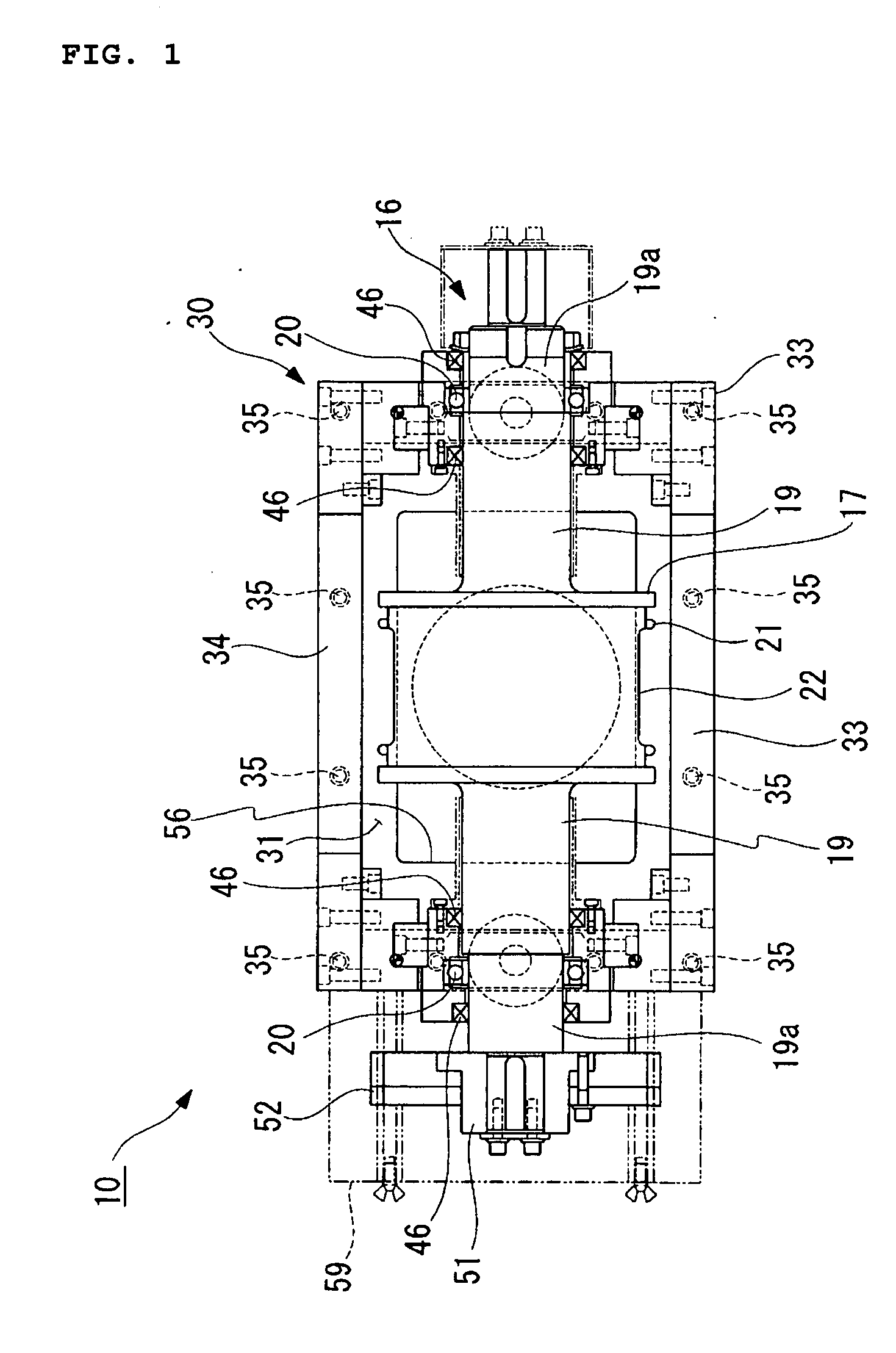
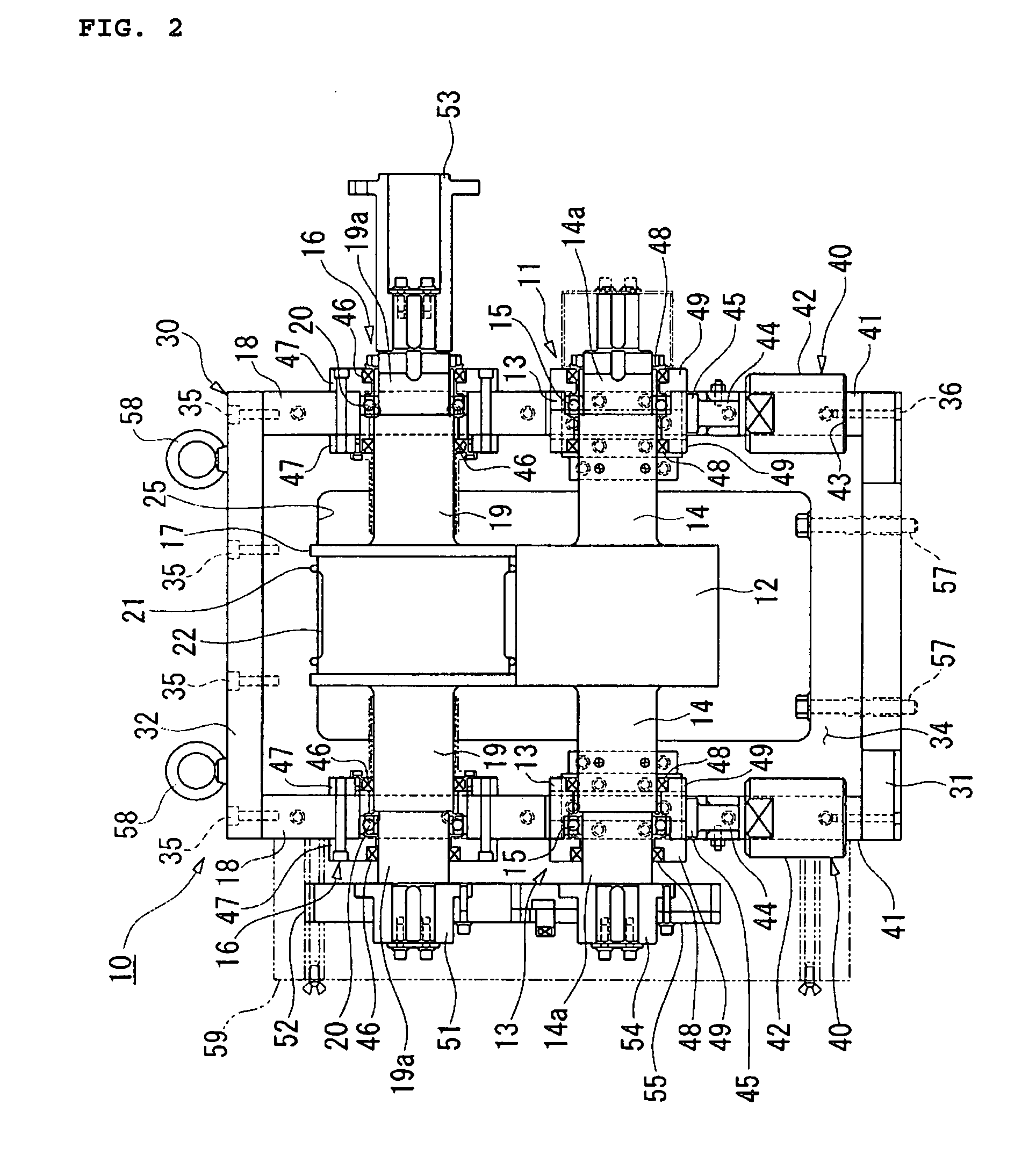
[0018] Hereinafter, a preferred embodiment of the invention will be described with reference to the drawings. FIGS. 1 to 4 show a rotary die device according to an embodiment of the invention. FIG. 1 is a plan view showing the rotary die device, FIG. 2 is a front view showing the rotary die device, FIG. 3 is a side view showing the rotary die device, and FIG. 4 is a perspective view illustrating a state in which a movable unit and a fixed unit of the rotary die unit cut a workpiece.

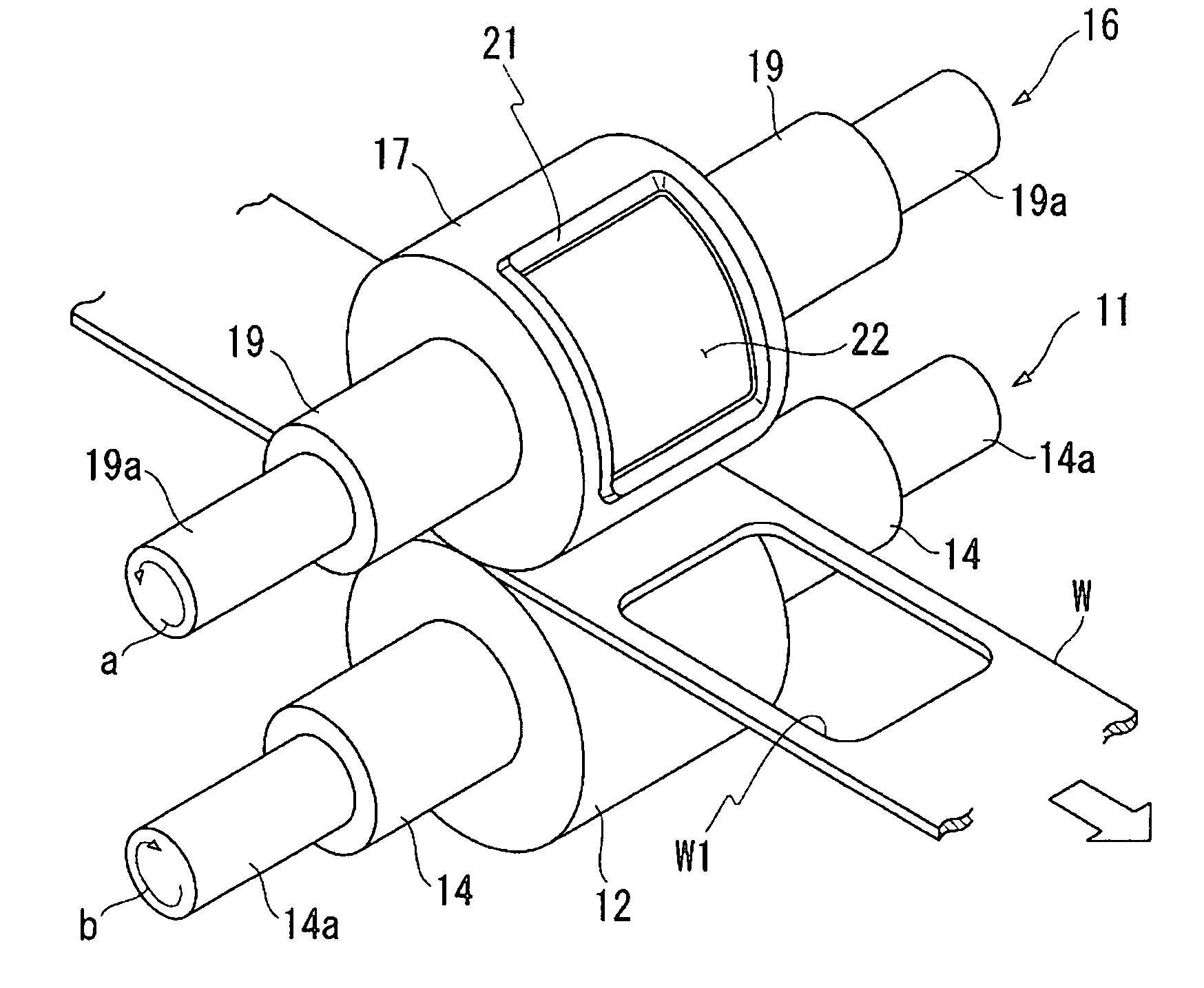
[0019] The rotary device 10 shown in FIGS. 1 to 3 includes a movable unit 11 and a fixed unit 16, and an anvil 12 of the movable unit 11 and a die 17 of the fixed unit 16 are rotated in opposite directions to each other, respectively, so that the workpiece is cut therebetween.

[0020] As shown in FIG. 2, the movable unit 11 is composed of the anvil 12 and supporters 13. The anvil 12 is a roller, and is rotatably supported by the supporters 13. As shown in FIGS. 2 and 4, the anvil 12 has an appropriate dia...


PUM

PropertyMeasurementUnit
shapeaaaaaaaaaa
cutting forceaaaaaaaaaa
diameteraaaaaaaaaa

Abstract

A movable unit, a fixed unit, and advance / retreat units are supported by a supporting structure. The supporting structure includes a base plate, a top plate, a front plate, and a rear plate. Between the front plate and the rear plate of the supporting structure, supporters of the movable unit are fixed by bolts, and supporters of the fixed unit are fixed by bolts above the movable unit. This prevents the axes of a fixed unit and a movable unit from being misaligned with each other. In addition, it also prevents looseness from being generated between the both units, thus preventing the life span of blades from being shortened.

Description

CROSS-REFERENCE TO PRIOR APPLICATION [0001] This is a U.S. National Phase Application under 35 U.S.C. §371 of International Patent Application No. PCT / JP2004 / 011760 filed Aug. 17, 2004, and claims the benefit of Japanese Patent Application No. 2003-209139 filed Aug. 27, 2003, both of them are incorporated by reference herein. The International Application was published in Japanese on Mar. 10, 2005 as WO 2005 / 021224 A1 under PCT Article 21(2).BACKGROUND OF THE INVENTION [0002] 1. Field of the Invention [0003] The present invention relates to a rotary die device, and particularly, to a rotary die device that cuts a workpiece in a desired shape between a pair of rollers rotated in opposite directions to each other. [0004] 2. Description of the Related Art [0005] In general, as a cutting device used for processing a sanitary product, it has been known a rotary die device having a fixed unit and a movable unit in which the axes are parallel to each other. The rotary die device cuts a wor...

Claims


Application Information

Patent Timeline
Patent Type & Authority Applications(United States)
IPC IPC(8): B26D7/20B26F1/38
CPCB26F1/384B26D7/265Y10T83/9312
Inventor TAKAHASHI, KAZUHIKOFUKUDA, TSUTOMUARAKAWA, KUNIAKI
Owner MITSUBISHI MATERIALS CORP
Why Eureka
Try Eureka