Fuel cell stack

a fuel cell and stack technology, applied in the field of fuel cells, can solve the problems of fuel cell interference with the external restraining member, difficult to ensure the necessary contact pressure between the fuel cells,

Inactive Publication Date: 2007-02-22
TOYOTA JIDOSHA KK
View PDF10 Cites 22 Cited by
  • Summary
  • Abstract
  • Description
  • Claims
  • Application Information

AI Technical Summary

Benefits of technology

[0052] According to the fuel cell stack in items (16) and (17) above, since a deformation preventing member is disposed between the extended portions of the opposite end fuel cells of the multi-cell module, the exten

Problems solved by technology

However, the following problems with the above fuel cell stack exist:
ii) In the case where the modules are held from the outside by the external restraining member, when the MEA and the diffusion layers of the fuel cell cause a creep receiving the spring force and the fuel cell near the end of the fuel cell stack mov

Method used


Image

  • Fuel cell stack
  • Fuel cell stack
  • Fuel cell stack

Examples


embodiment 1

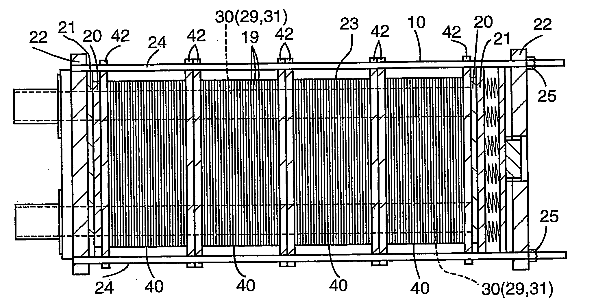
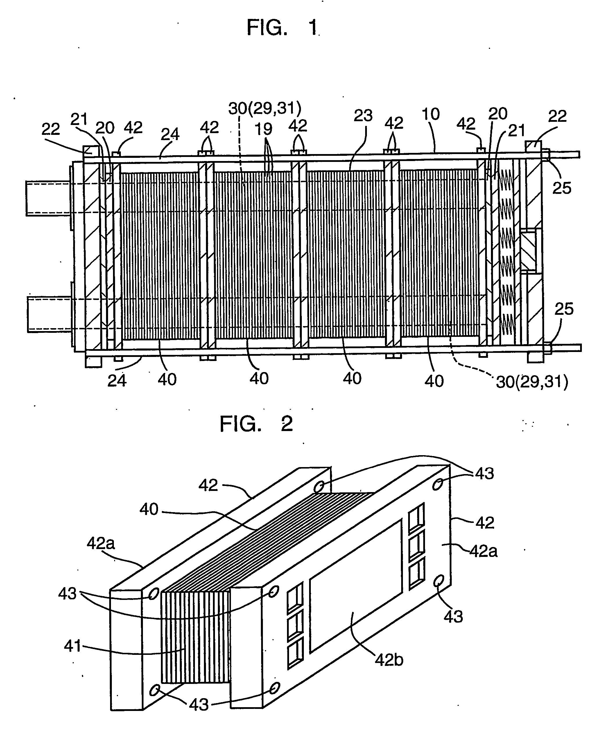
[0110] In embodiment 1 of the present invention, as illustrated in FIGS. 1-4, the extended portion 42a of the end fuel cell 42 is made from synthetic resin and the separator portion 42b of the end fuel cell 42 is made from metal, for example, stainless steel. The holes 43 are provided at the four corners of the rectangular extended portion 42a.

[0111] The individual fuel cells of the multi-cell assembly 41 of the multi-cell module 40 is adhered to each other by the adhesive seal 33. The seal between the adjacent multi-cell modules 40 (between a multi-cell module and its multi-cell module) is a rubber gasket 32.

[0112] The fastening shaft 24 which is commonly used as the restraining shaft 24 extends through the hole 43 formed in the extended portion 42a and restrains the multi-cell module 40 in the direction perpendicular to the fuel cell stacking direction. Since the extended portion 42a of the end fuel cell 42 is made from synthetic resin, the extended portion 42a is electrically i...

embodiment 2

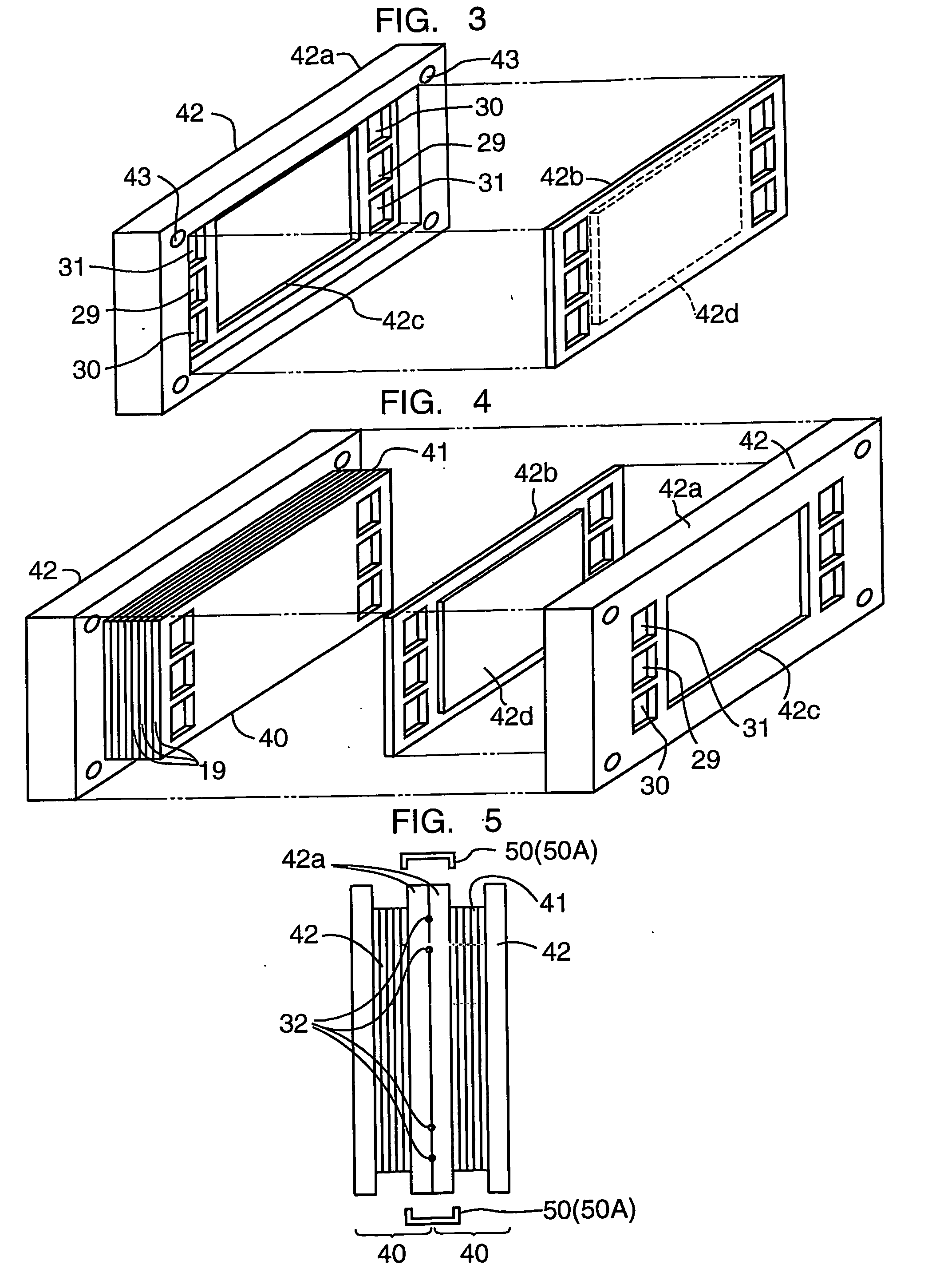
[0116] In embodiment 2 of the present invention, as illustrated in FIGS. 5-7, the end fuel cells 42 of adjacent multi-cell modules 40 are connected by a connecting member 50 that is different from the fastening shaft 24. In Embodiment 2 of the present invention, the connecting member 50 is a clip 50A. The clip 50A may have or may not have elasticity.

[0117] With respect to effects and technical advantages of embodiment 2 of the present invention, the rubber gasket 32 seals between the adjacent multi-cell modules 40 and adhesive seal 33 seals between the fuel cells in each multi-cell module. When the spring force of the spring located at an end of the stack acts on the multi-cell modules 40, and if the opposing end fuel cells 42 of the adjacent multi-cell modules 40 do not have a sufficient rigidity, the opposing end fuel cells 42 will be deformed in a direction away from each other. As a result, a necessary seal force is not imposed on the rubber gasket 32.

[0118] However, in embodi...

embodiment 3

[0119] In embodiment 3 of the present invention, as illustrated in FIGS. 8 and 9, the end fuel cells 42 of adjacent multi-cell modules 40 are connected by the connecting member 50 which is different from the fastening shaft 24. In embodiment 3 of the present invention, the connecting member 50 is a bolt 50B or a rivet.

[0120] The effects and technical advantages of embodiment 3 of the present invention are discussed below. In the case where the seal between the fuel cells of each multi-cell module 40 is an adhesive seal and the seal between the adjacent multi-cell modules 40 is a rubber gasket 32, if the end fuel cells 42 of the adjacent multi-cell modules do not have a sufficient rigidity, a sufficient seal force cannot be given to the rubber gasket 32.

[0121] However, in embodiment 3 of the present invention, since the opposing end fuel cells 42 of the adjacent multi-cell modules 40 are pressed against each other by the bolt SOB or a rivet at the extended portions 42a, a sufficien...


PUM


Abstract

A fuel cell stack includes a plurality of multi-cell modules stacked and a restraining member. Each multi-cell module includes a plurality of fuel cells including opposite end fuel cells at opposite ends of the plurality of fuel cells layered. The restraining member restrains the multi-cell module in a direction perpendicular to the fuel cell stacking direction at the opposite end fuel cells of each multi-cell module. Each of the opposite end fuel cells has an extended portion formed by extending the opposite end fuel cell outwardly in a direction perpendicular to the fuel cell stacking direction, and each multi-cell module is restrained by the restraining member at the extended portion. A hole is formed in the extended portion and a restraining shaft defining the restraining member extends through the hole. A deformation preventing member may be disposed between the extended portions.

Description

FIELD OF INVENTION [0001] The present invention relates to a fuel cell. More particularly, the present invention relates to a fuel cell stack structure. BACKGROUND OF THE INVENTION [0002] As illustrated in Japanese Patent Publication No. 2002-124291, and as illustrated in FIGS. 16 and 17, a fuel cell, for example, a Polymer Electrolyte Fuel Cell (PEFC) apparatus 10 includes a layering structure of a Membrane-Electrode Assembly (MEA) and a separator 18. The layering direction may be in any direction. [0003] The MEA includes a an electrolyte membrane 11 made from an ion exchange membrane and a pair of electrodes which includes an anode 14 disposed on one side of the electrolyte membrane and a cathode 15 disposed on the other side of the electrolyte membrane. A diffusion layer 13 may be disposed between the anode and the separator 18, and a diffusion layer 16 may be disposed between the cathode and the separator 18. [0004] A first separator 18 disposed on one side of the MEA has a fuel...

Claims


Application Information

Patent Timeline
IPC IPC(8): H01M8/24H01M8/02H01M8/10
CPCH01M8/248Y02E60/50
Inventor INAGAKI, TOSHIYUKI
Owner TOYOTA JIDOSHA KK
Why Eureka
Try Eureka