
Fluid operated position regulator

a technology of position regulator and flue, which is applied in the direction of valve details, instruments, and flue pressure control, can solve the problem of relative difficulty in exactly setting the control, and achieve the effect of simple means

Inactive Publication Date: 2007-03-01
FESTO AG & CO KG
View PDF10 Cites 49 Cited by
  • Summary
  • Abstract
  • Description
  • Claims
  • Application Information

AI Technical Summary

Benefits of technology

The present invention is a space-saving fluid operated position regulator that ensures an exact control of a power device. The regulator has two fluid actuating faces, each with a common control pressure connection. The two control chambers are connected downstream from the control pressure connection with a venting opening, which is controlled by an electrically actuated control valve. The valve can open or close both venting openings simultaneously. The design ensures that the servo means compensates for fluid forces when the two control chambers are connected with a common control pressure connection. The control valve is a piezoelectric valve, which allows for a continuous, stepless actuation and a large range of strokes. The two fluid actuating faces are located on two diaphragm elements, and the servo member is axially biased by two oppositely acting spring means. The invention provides a compact, space-saving, and easy-to-install position regulator.

Problems solved by technology

Since the position regulator is so designed that the servo means assumes the venting position in the case of a control pressure being equal to the pressure of the surroundings, it is relatively difficult to exactly so set the control pressure that there is a closed state separating the power connection simultaneously from the two other connections and entailing a constant position of the power device which is connected.

Method used


Image

  • Fluid operated position regulator
  • Fluid operated position regulator
  • Fluid operated position regulator

Examples


Embodiment Construction

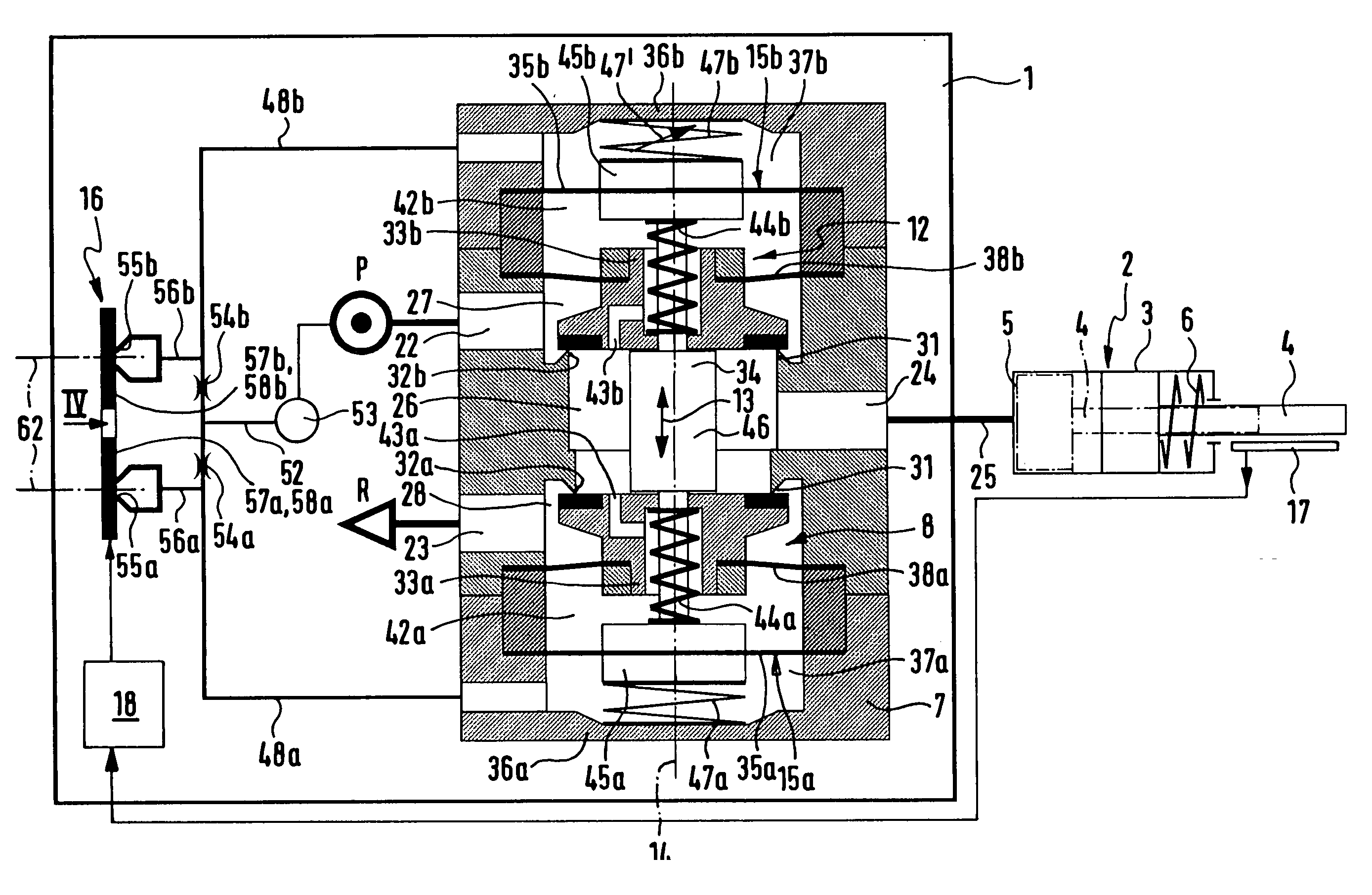
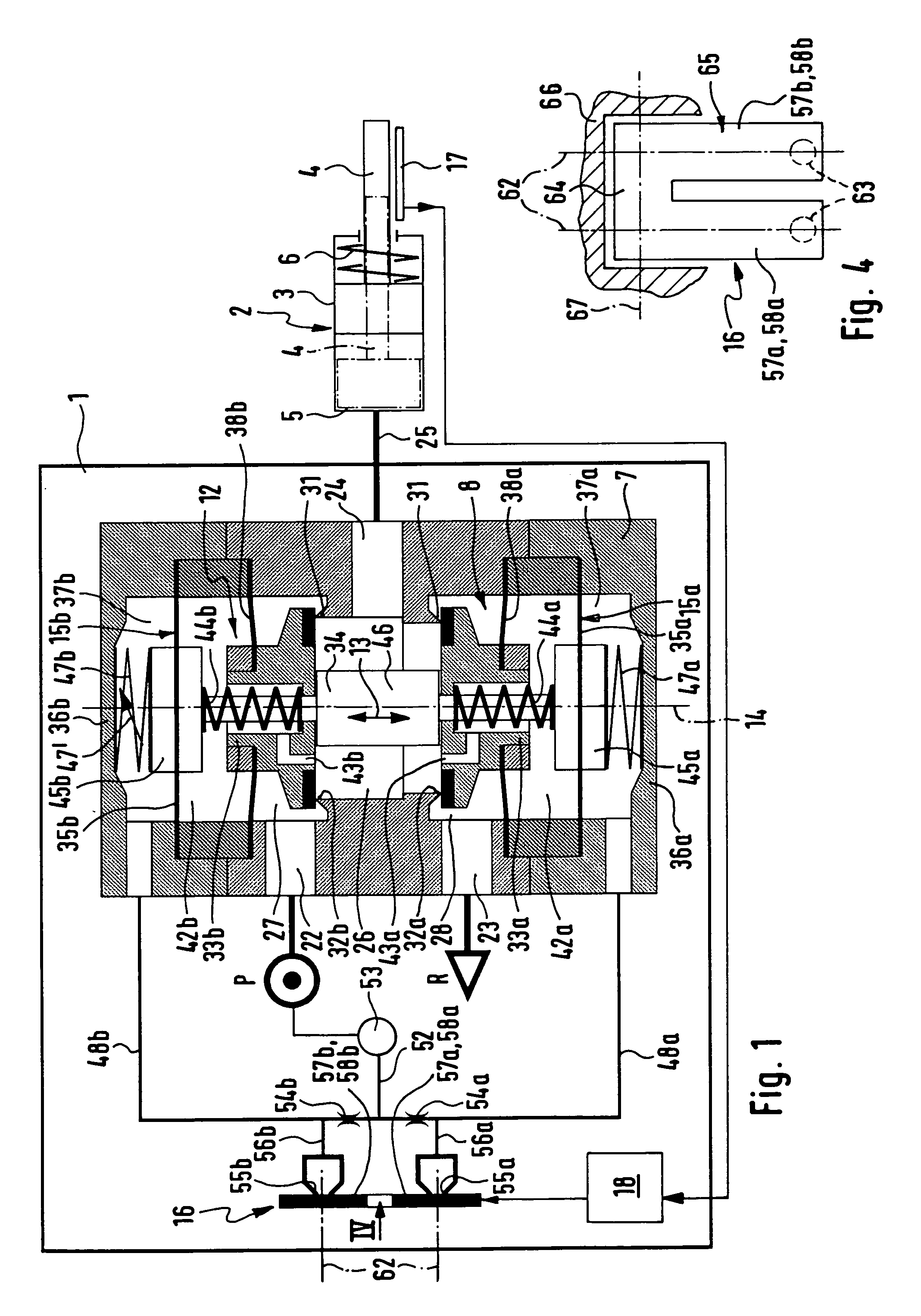
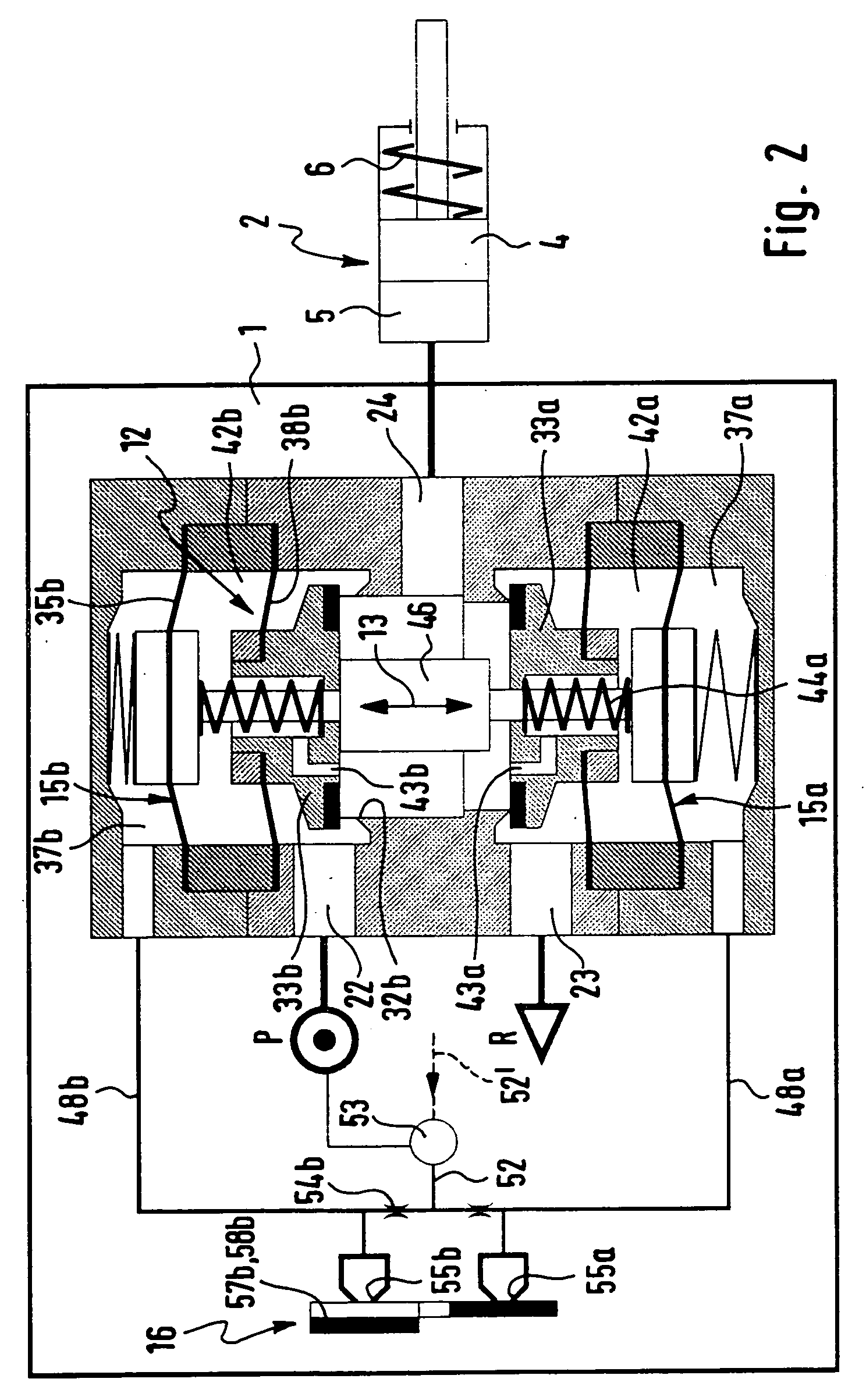
[0023] The fluid operated position regulator generally referenced 1 is designed in the form of one structural unit wherein the individual components are compactly nested together. It is merely for the sake of a straightforward synoptic view that the individual components in the drawing are illustrated within the rectangular frame defining the position regulator 1.

[0024] As shown in FIGS. 1 through 3 there is furthermore a power device 2 or load able to be controlled by the position regulator 1, in the case of which in the present example it is a question of a single acting fluid power drive of a process valve, not illustrated in detail, with its further components. The power device 2 comprises a housing 3 and an outlet part 4 able to be linearly shifted or also shifted in rotation in relation to the housing 3, the outlet drive part 4 defining in conjunction with the housing 3 a drive chamber 5 able to be put under pressure medium pressure against the return force of the spring mean...


PUM


Abstract

A fluid operated position regulator comprises a servo means, arranged in a regulator housing and by which a supply connection, a venting connection and a power connection can be placed in circuit in an adjustable manner. To predetermine or set its position the servo means possesses two mutually oppositely orientated fluid actuating faces of equal size, which respectively delimit a control chamber. The two control chambers are connected by way of an intermediately placed choke means with a common control pressure connection. Downstream from the two choke means each control chamber is connected with a venting connection. A control valve means can control the two venting connections and in particular simultaneously close them.

Description

CROSS-REFERENCE TO RELATED APPLICATION [0001] This application claims priority based on European Patent Application No. 05 018 231.0 filed on Aug. 23, 2005, which is incorporated herein by reference. BACKGROUND OF THE INVENTION [0002] 1. Field of the Invention [0003] The invention relates to a fluid operated position regulator for power devices and in particular for process valves, comprising a regulator housing, in which at least one servo means, which is able to be shifted by controlled fluid actuation with the performance of a positioning movement, is arranged, said servo means being able, in a fashion dependent on its position, to place, in different manners, a supply opening, a venting opening and a power connection provided for the connection of the power device, in a fluid circuit with each other. [0004] 2. Description of the Related Art [0005] A position regulator disclosed in the European patent publication 0 726 511 B1 of this type comprises a servo means arranged in a reg...

Claims


Application Information

Patent Timeline
Patent Type & Authority Applications(United States)
IPC IPC(8): F16K31/02
CPCG05D16/163F15B13/0405F15B13/0433F15B2211/3057F15B2211/7052Y10T137/8659
Inventor WIRTL, HANNESMAICHL, MARTINFRISCH, HERBERT
Owner FESTO AG & CO KG
Learn More