Storage cabinet with improved RFID antenna system

a technology of rfid tracking system and storage cabinet, which is applied in the direction of burglar alarm by hand-held articles removal, burglar alarm mechanical actuation, etc., can solve the problems of multiple antennas, creating additional nulls, and not useful traditional “far field analysis of antenna systems, so as to improve the manufacturability of pc boards, easy and quick repositioning, and the effect of improving the ease of moving shelves

Inactive Publication Date: 2007-03-01
BLACK & DECKER INC
View PDF26 Cites 40 Cited by
  • Summary
  • Abstract
  • Description
  • Claims
  • Application Information

AI Technical Summary

Benefits of technology

[0011] Currents created in one part of the figure eight antenna due to coupling with the loop antenna are offset by equal and opposite current created in another portion of the figure eight antenna. Similarly, currents created within the loop antenna due to coupling with one portion of the figure eight antenna are countered by equal and opposite currents created by coupling with another portion of the figure eight antenna. Thus, nulls created by the coupling between the figure eight antenna and the loop antenna are substantially reduced. Since the nulls between the two antennas are minimized, it is possible to place the two antennas in relatively close proximity, thereby allowing the near-field coverage of the two antennas to be maximized.
[0018] The resultant system has high accuracy detecting RFID tagged items placed on the shelf. Additionally, the shelves are easily movable, allowing a cabinet or shelf system to be adaptable so as accommodate a variety of articles.

Problems solved by technology

Because an RFID antenna system within a shelf is to be effective within a relatively small area, traditional “far field” analysis of the antenna systems is not useful.
Multiple antennas, however, present an additional problem.
Antennas in close proximity couple, thereby creating additional nulls.
This is especially problematic in the near field since the coupling between the antennas can be particularly strong.
Some medical supplies are extremely expensive, costing several thousand dollars per item.
Medical RFID systems previously proposed are expensive, involving elaborate storage containers made specifically for scanning RFID equipped articles.
The containers cannot be easily adjusted to accommodate different size articles.
Additionally, the RFID systems are not easily moved from one location to another.
Further, the accuracy of current RFID systems for use in medical facilities is less than desirable.

Method used


Image

  • Storage cabinet with improved RFID antenna system
  • Storage cabinet with improved RFID antenna system
  • Storage cabinet with improved RFID antenna system

Examples


Embodiment Construction

[0030] An antenna assembly constructed in accordance with the current embodiment of the invention is illustrated in the drawings as well as shelves containing the antenna assembly and a cabinet for use with the shelves.

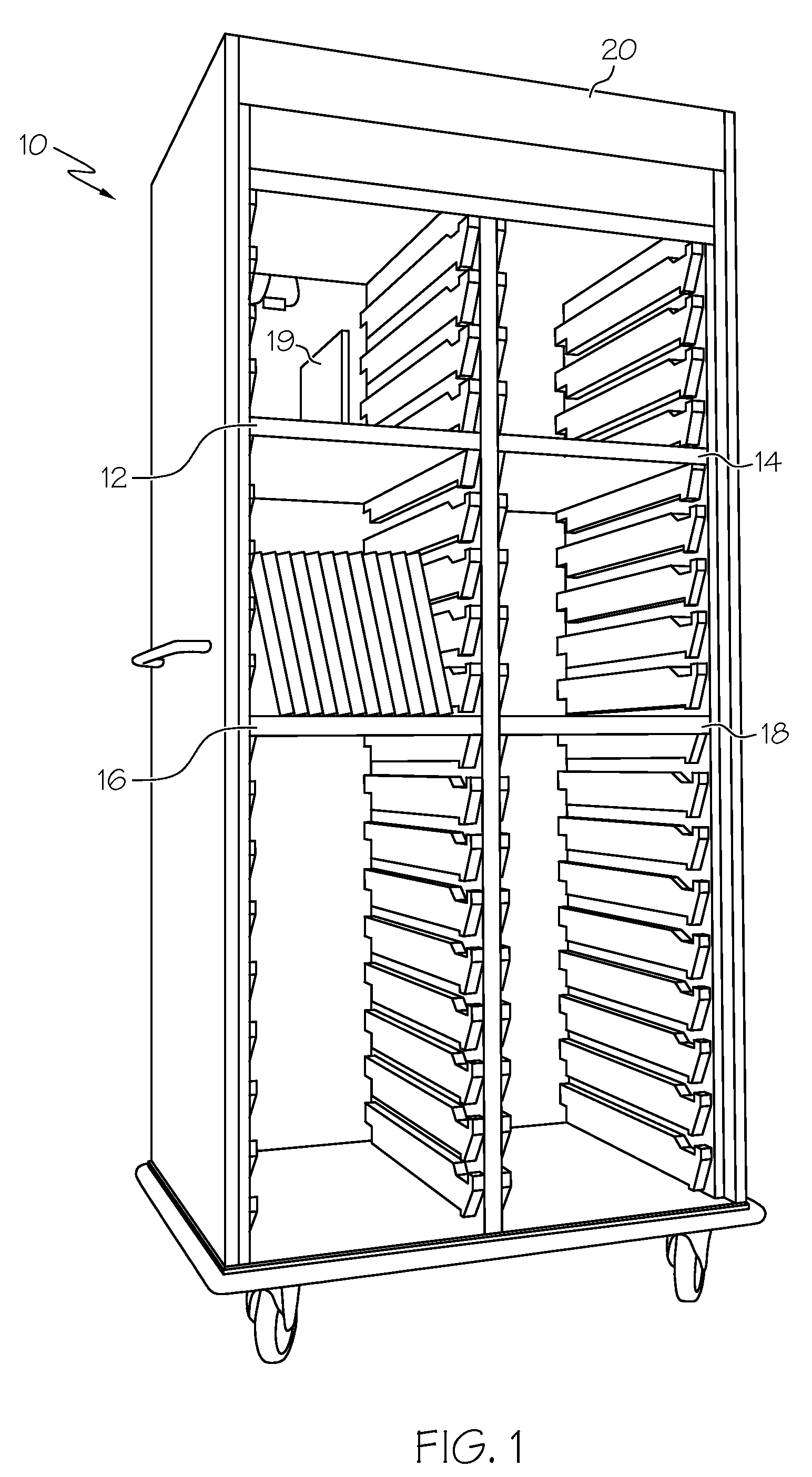
[0031] A cabinet 10 for holding a variety of different sized articles is show in FIG. 1. The cabinet 10 includes several repositionable shelves 12, 14, 16, 18. The shelves 12, 14, 16, 18 can be positioned at various locations within cabinet 10. A divider 19 can also be located in the middle of a shelf. Alternatively, multiple dividers could be used on a shelf.

[0032] The antenna assemblies described hereinafter may be placed within the shelves 12, 14, 16, 18 and the divider 19, thereby allowing an RFID reader to read the RFID tags of articles placed within cabinet 10.

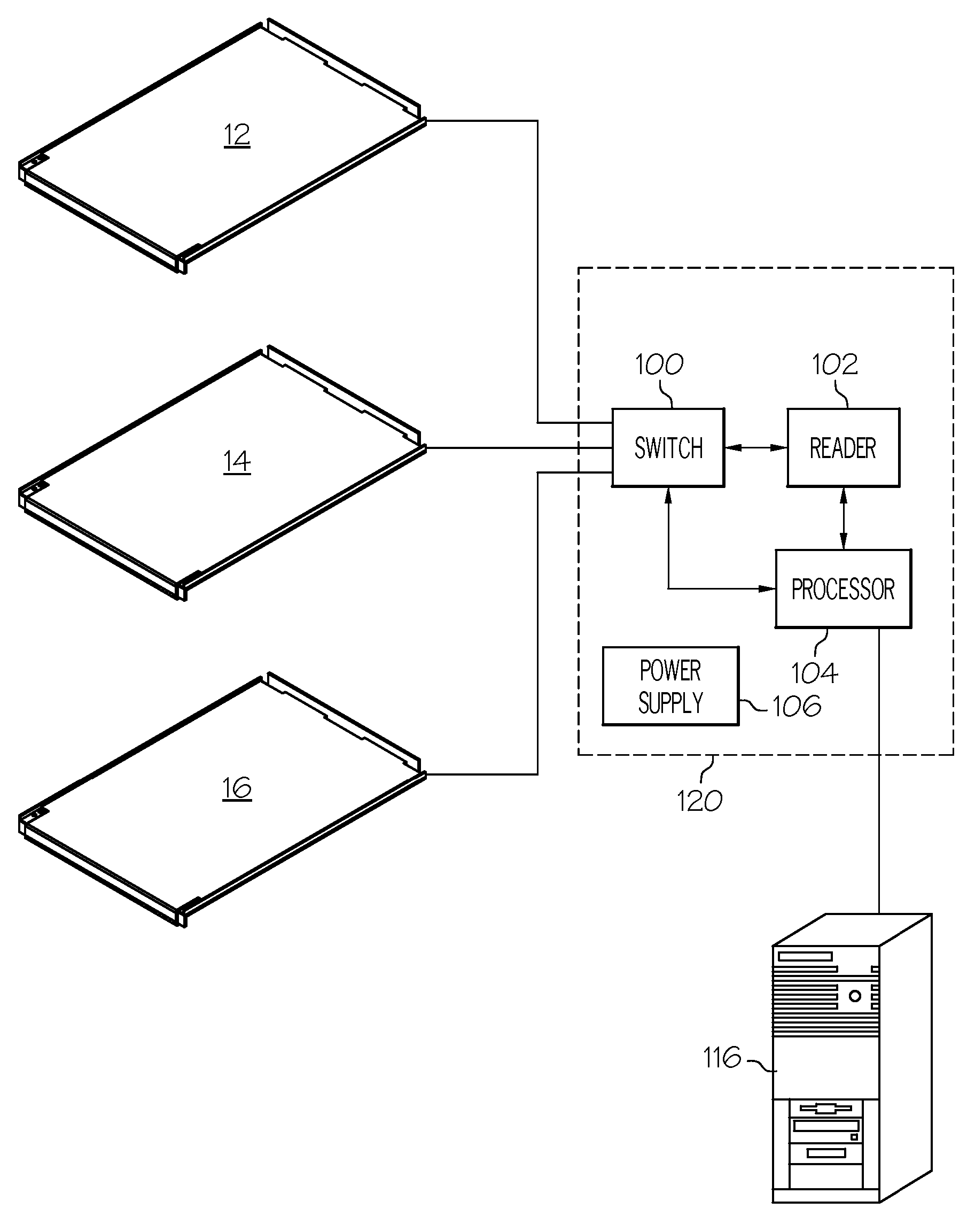
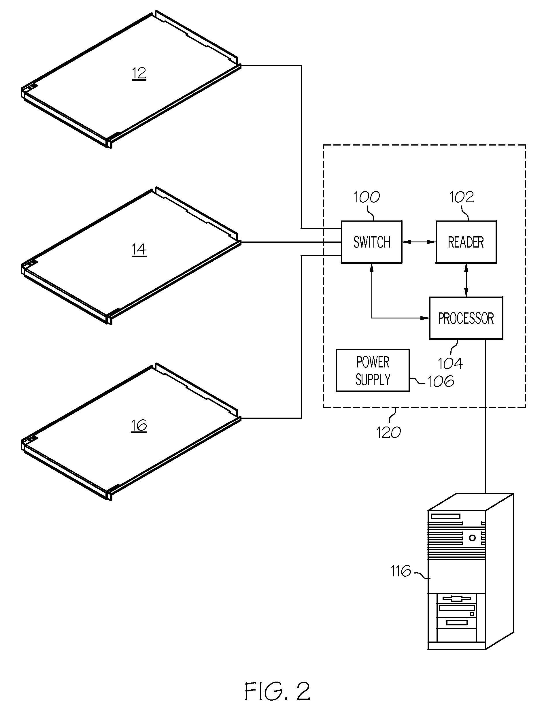
[0033] Various electronic devices associated with reading RFID tags can be placed within the top 20 of the cabinet 10. For example, a switch, an RFID reader and a processor can be placed within the top ...


PUM


Abstract

A system for reading RFID tags of articles within a cabinet includes a repositionable shelf. The repositionable shelf includes an antenna assembly having three antenna pairs. Each antenna pair has a loop antenna and a figure eight antenna. The antenna pairs are on a PC board. The PC board includes an RJ45 connector which provides both power to the antenna assembly as well as a communication interface for the antenna assembly. The RJ45 connector could be used to provide the RF signals from the antenna to a reader. The system could also include a repositionable divider for placement perpendicular to the repositionable shelf. The repositionable divider also includes a loop antenna and a figure eight antenna.

Description

PRIORITY CLAIM [0001] This application claims priority from U.S. Provisional Application No. 60 / 713,545, filed Aug. 31, 2005, entitled “RFID Shelf Incorporating Planar Complementary Antennas”.BACKGROUND OF THE INVENTION [0002] This invention relates to item tracking systems and inventory management and more particularly to an antenna assembly for use with an RFID tracking system. [0003]“Smart shelves” refer to systems used to identify articles equipped with a radio frequency identification (RFID) transponder, or “tag”. Smart shelf systems are capable of determining the number, identity, and location of RFID tagged items placed on a store shelf, book shelf, or in a cabinet. When these shelves or other fixtures are equipped with one or more antennas coupled to an RFID interrogator, the contents of an article's tag may be read by the RFID interrogator. The number and location of each article may then be obtained and the location and use of the article tracked. Out of stock situations m...

Claims


Application Information

Patent Timeline
Patent Type & Authority Applications(United States)
IPC IPC(8): H01Q1/00G08B13/14G16H40/20
CPCG06Q10/08G06Q10/087G06Q50/22H01Q7/00H01Q1/2216H01Q1/44G06Q50/28G16H40/20
Inventor MARINO, RONALD A.
Owner BLACK & DECKER INC
Why Eureka
Try Eureka