Pixilated LED Light Source for Channel Letter Illumination

a led light source and channel letter technology, applied in the direction of light source combinations, identification means, instruments, etc., can solve the problems of affecting intensity, lessening led life, and not allowing efficient heat dissipation of channel letters, so as to reduce energy consumption and heat generation.

Inactive Publication Date: 2008-04-03
CAO GROUP
View PDF32 Cites 21 Cited by
  • Summary
  • Abstract
  • Description
  • Claims
  • Application Information

AI Technical Summary

Benefits of technology

[0004]In view of the foregoing disadvantages inherent in the known types of LED lighting modules, this invention provides an improved LED lighting module that reduces both energy consumption and heat generation by using LEDs previously though too small for channel letter signage purposes.
[0005]To accomplish these objectives, the modules comprise an outer casing, ideally made of plastic, with an internal printed circuit board and driving circuit. Small, through-hole LEDs protrude through an upper surface of the module in a formation called a pixel, where the entire pixel is designed to replace a single LED as used in prior art applications. As such, the LEDs have a larger beam angle than prior art LEDs (which tend to be more focused) and the pixel shape in and of itself is chosen to maximize coverage. The modules according to the present invention generate significantly less heat than prior art modules, so a heat sink is unnecessary, leaving out a significant cost and weight to the modules.

Problems solved by technology

Channel letter construction typically does not allow for efficient dispersion of heat as the letter forms are typically closed with tight interiors.
Heat sinks, however, collect heat and are typically a slow way to dissipate heat.
Unfortunately, excess heat tends to lessen LED life and affect intensity, so added heat has a deleterious effect on LED signage.

Method used


Image

  • Pixilated LED Light Source for Channel Letter Illumination
  • Pixilated LED Light Source for Channel Letter Illumination
  • Pixilated LED Light Source for Channel Letter Illumination

Examples


Embodiment Construction

[0013]With reference now to the drawings, the preferred embodiment of the pixilated LED lighting module is herein described. It should be noted that the articles “a”, “an” and “the”, as used in this specification, include plural referents unless the content clearly dictates otherwise.

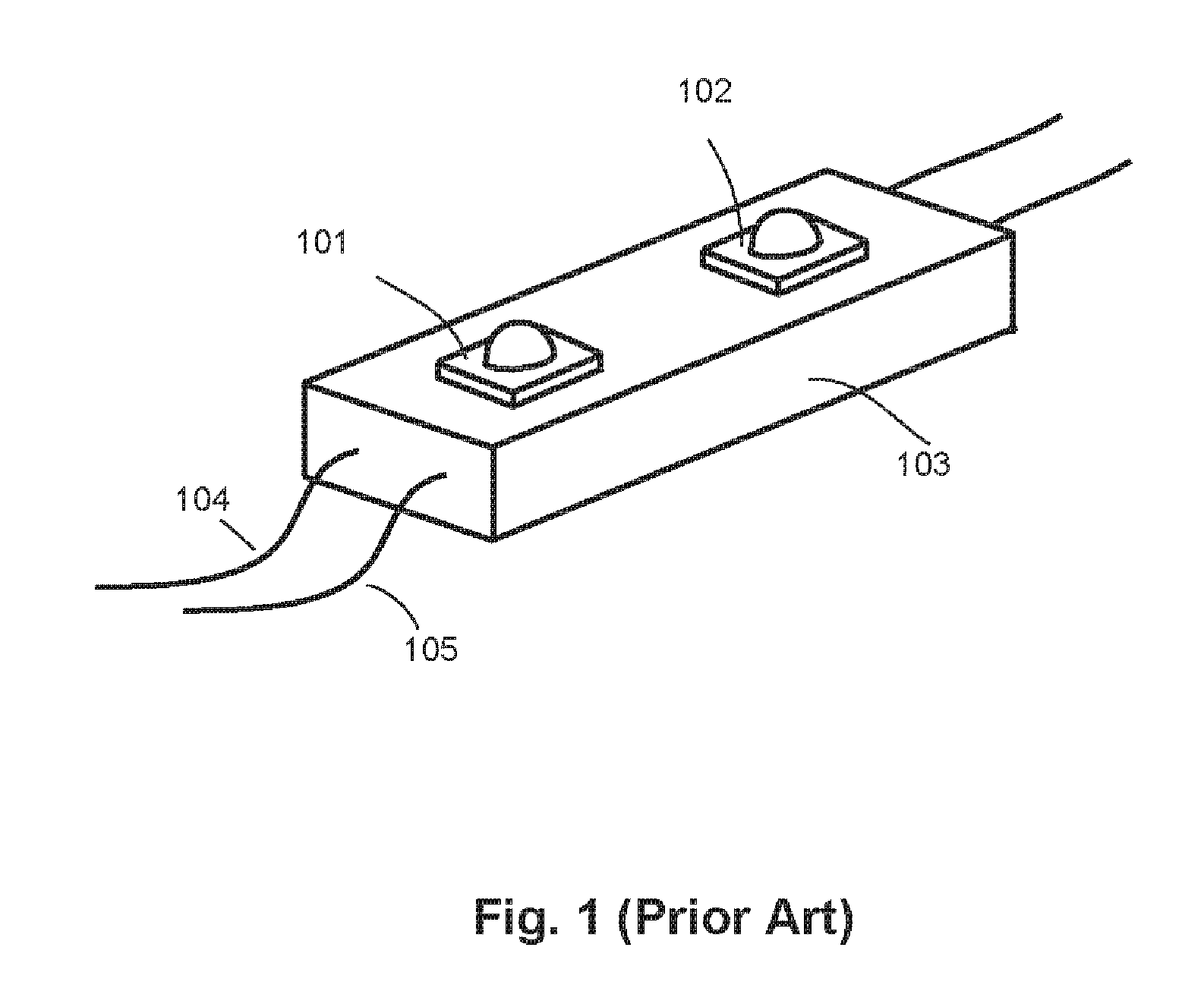
[0014]FIG. 1 depicts prior art, using piranha LEDs as light source for channel letter illumination. This format, using such large surface mounted LEDs 101, 102 as a light source, is widely used in the market. LEDs 101 and 102 in this example are piranha LEDs mounted on the upper surface of module 103. Most of the module 103 is metal to dissipate the heat generated by piranha LEDs 101 and 102. A plurality of modules 103 are electrically connected by wires 104, 105 and mounted in a channel letter for signage illumination. The disadvantage of this light source is that the both the intensity of emitted light and the covering angle are limited. Another issue is that a high input current has to be used with p...


PUM


Abstract

The present invention is an LED module for channel letter illumination utilizing multiple through-hole LEDs in a pixel formation as a light source where one surface mounted LED or other forms of LEDs were previously used. The use of a number of small through-hole LEDs ideally requires that a beam angle between and including 15° and 180° in vertical and horizontal directions, respectively, be utilized. When multiple light sources are used on a module, the distance between light sources is to be between 20 mm and 1 cm. The use of several smaller LEDs reduces the current needed to generate light of appropriate intensity and, thus reduces energy cost and heat generation. The use of smaller LEDs also assists in excess heat dissipation.

Description

FIELD OF THE INVENTION[0001]The present invention relates to the field of channel letter illumination and more particularly relates to an efficient use of a customized through-hole LEDs to provide channel letter illumination.BACKGROUND OF THE INVENTION[0002]In recent years, LEDs have been used in commercial signage applications, particularly in channel letters in place of neon and other fluorescent lighting. One common construction of LED signage involves mounting at least one LED on a small module that can be attached in a string of such modules into channel letter forms. The string of modules is formed by each module and wires connecting them together, forming a relatively flexible lighted strand of LEDs for use in these applications. Each module must be constructed to withstand and disperse the heat generated by a single LED at it is powered to achieve useful intensity. Channel letter construction typically does not allow for efficient dispersion of heat as the letter forms are t...

Claims


Application Information

Patent Timeline
Patent Type & Authority Applications(United States)
IPC IPC(8): F21S13/14
CPCF21S2/005F21V31/04F21Y2101/02F21V23/005G09F9/33F21K9/30F21Y2113/005F21K9/20F21Y2115/10F21Y2113/13
Inventor CAO, DENSEN
Owner CAO GROUP
Why Eureka
Try Eureka