Write-in driving method for plasma display

a technology of write-in driving and plasma display, which is applied in the direction of instruments, static indicating devices, etc., can solve the problems of circuit design and complex structure, and achieve the effect of reducing the delay time for producing and increasing the voltag

Inactive Publication Date: 2007-03-01
CHUNGHWA PICTURE TUBES LTD
View PDF4 Cites 1 Cited by
  • Summary
  • Abstract
  • Description
  • Claims
  • Application Information

AI Technical Summary

Benefits of technology

[0014] Accordingly, at least one objective of the present invention is to provide a write-in driving method for a plasma display that utilizes the application

Problems solved by technology

Yet, if the number of preset pulses 510 is too many, then the preset pulse triggered electric discharge

Method used


Image

  • Write-in driving method for plasma display
  • Write-in driving method for plasma display
  • Write-in driving method for plasma display

Examples


Embodiment Construction

[0030] Reference will now be made in detail to the present preferred embodiments of the invention, examples of which are illustrated in the accompanying drawings. Wherever possible, the same reference numbers are used in the drawings and the description to refer to the same or like parts.

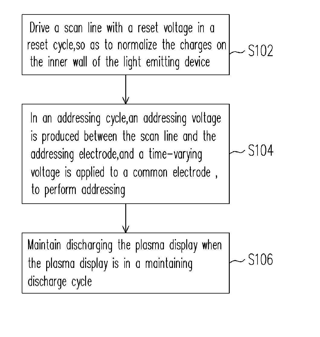
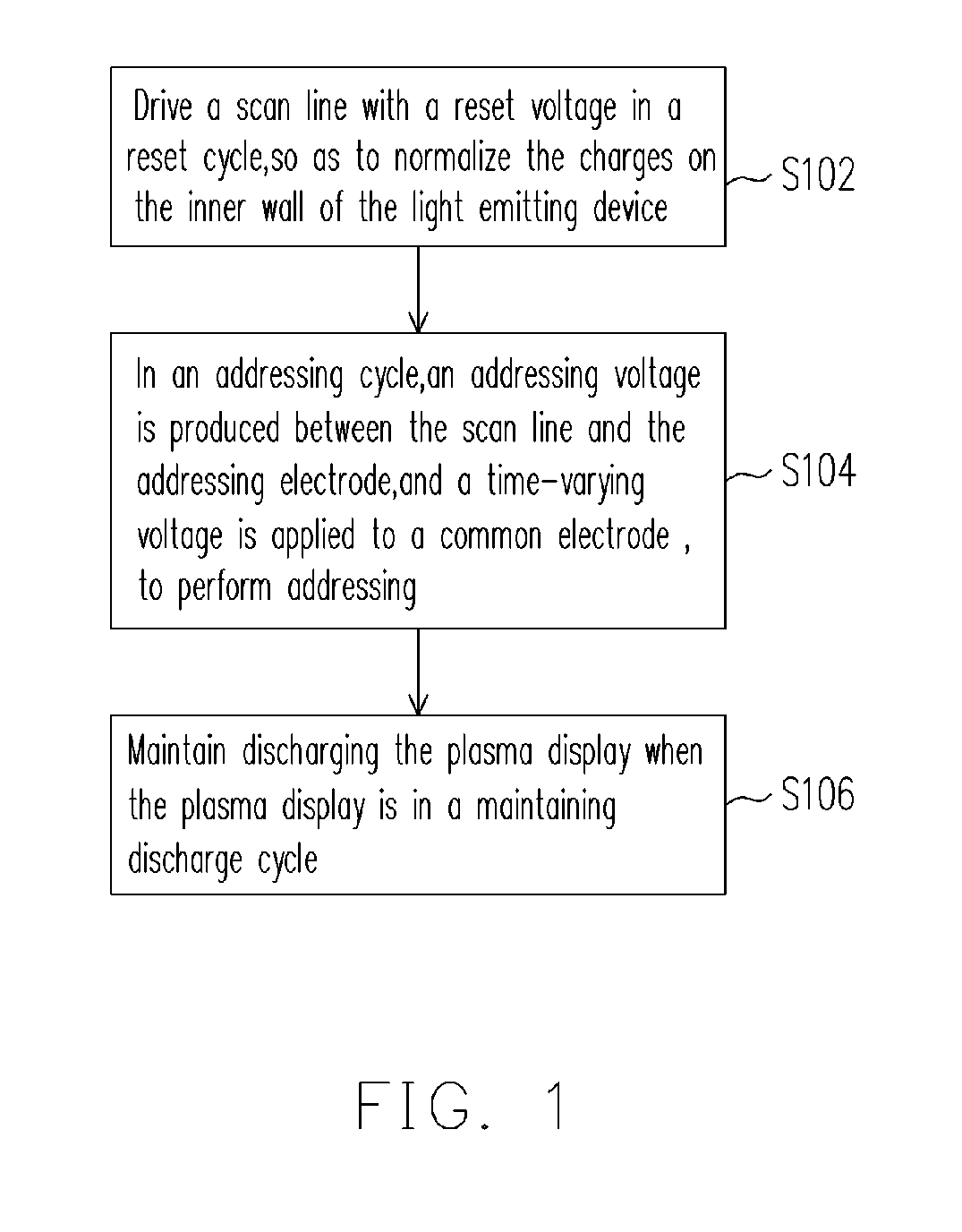
[0031]FIG. 1 is a flow diagram showing the steps in a write-in driving method for operating plasma display according to one preferred embodiment of the present invention. It should be known by anyone familiar with the technique that the plasma display might comprise a plurality of scan lines and at least a common electrode. However, this should by no means limit the scope of the present invention.

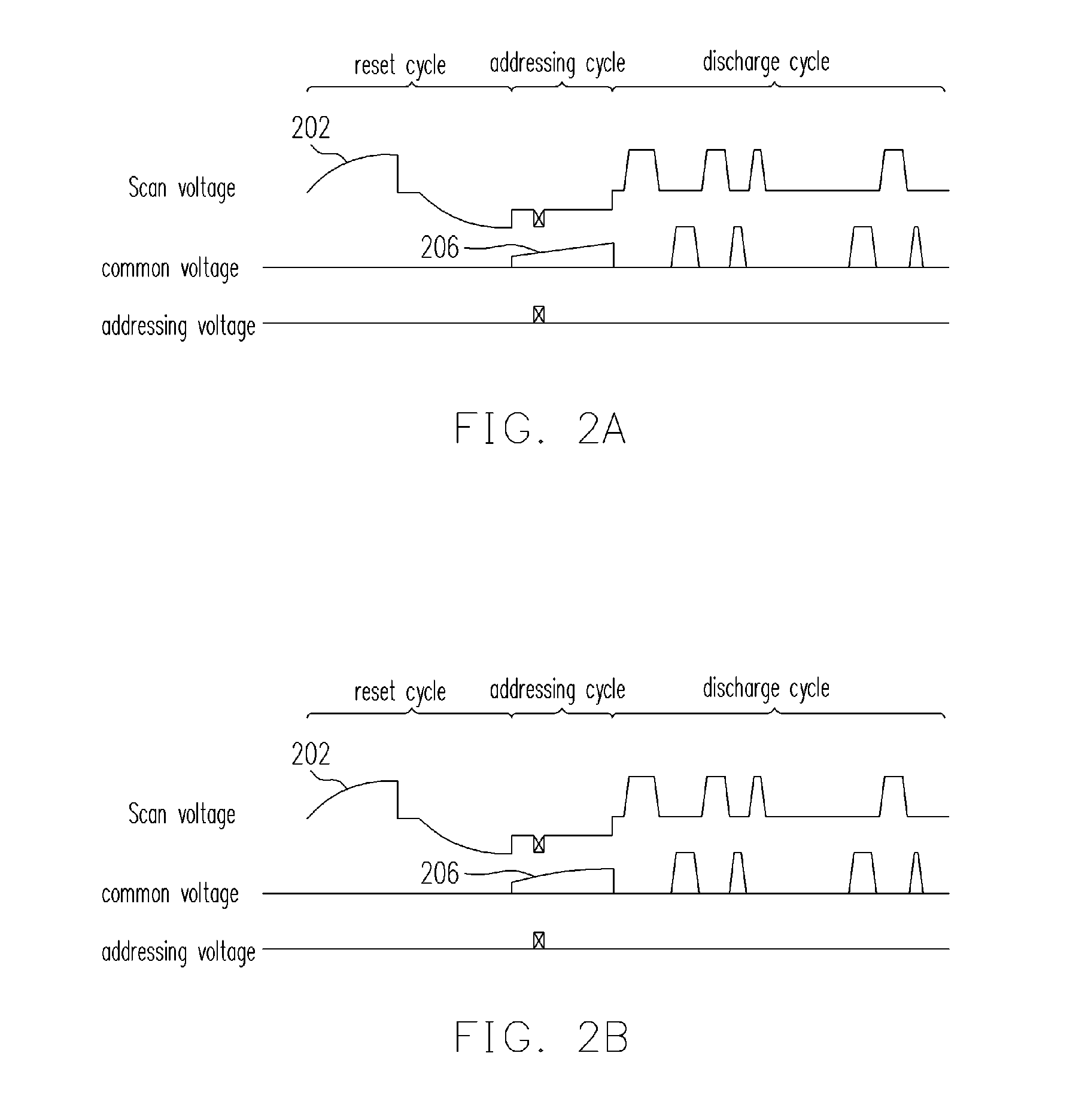
[0032] In the following description, refer to FIGS. 1, 2A and 2B. FIG. 2A is a diagram showing the write-in driving voltage waveform for operating a plasma device according to one preferred embodiment of the present invention. FIG. 2B is a diagram showing the write-in driving voltage waveform for operatin...


PUM


Abstract

An addressing driving method for a plasma display is described. The plasma display comprises at least a scan line and at least a common electrode. The addressing driving method uses the following driving scheme. Initially the plasma display is in a reset period, a scanning voltage is used to drive the scan line to equalize the wall charge distribution in cell. When the plasma display is in an addressing period, a time-varying common voltage is applied to the common electrode. Finally, the plasma display is in a sustain period, the display cells are sustained in discharge condition. The driving scheme not only discharge lag for high speed addressing but the voltage margin of the panel voltage is also increased.

Description

CROSS-REFERENCE TO RELATED APPLICATION [0001] This application claims the priority benefit of Taiwan application serial no. 94129923, filed on Aug. 31, 2005. All disclosure of the Taiwan application is incorporated herein by reference. BACKGROUND OF THE INVENTION [0002] 1. Field of the Invention [0003] The present invention relates to a write-in driving method for a plasma display. More particularly, the present invention relates to a plasma display having a write-in driving method that changes the common voltage applied to the common electrode with time when the plasma display is in an addressing cycle. [0004] 2. Description of the Related Art [0005] For an AC-PDP, the displaying principle is to apply a voltage at the grid point (cell) between an X-axis electrode and a Y-axis electrode. When the applied voltage is at the gas breakdown voltage (for example, about 180 volts), gaseous atoms will be ionized to produce ions. Thereafter, electrons accelerated to a high speed through the ...

Claims


Application Information

Patent Timeline
IPC IPC(8): G09G3/28
CPCG09G3/2932G09G2320/0228G09G3/298
Inventor HSU, CHAO-HUNG
Owner CHUNGHWA PICTURE TUBES LTD
Why Eureka
Try Eureka