

Image display apparatus and image adjusting method
- Summary
- Abstract
- Description
- Claims
- Application Information
AI Technical Summary
Benefits of technology
Problems solved by technology
Method used
Image

Examples
first embodiment
Overviews of Projector
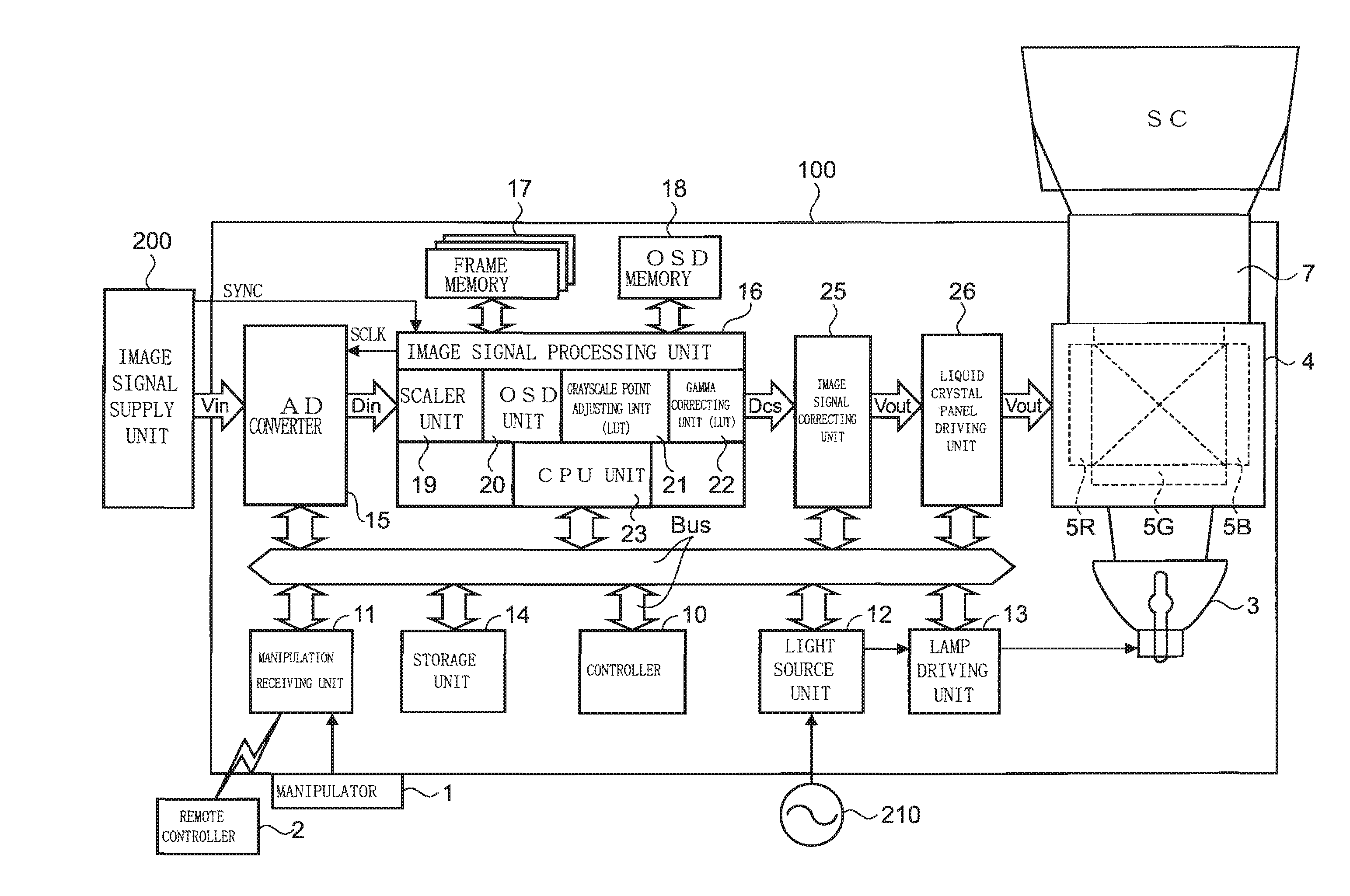
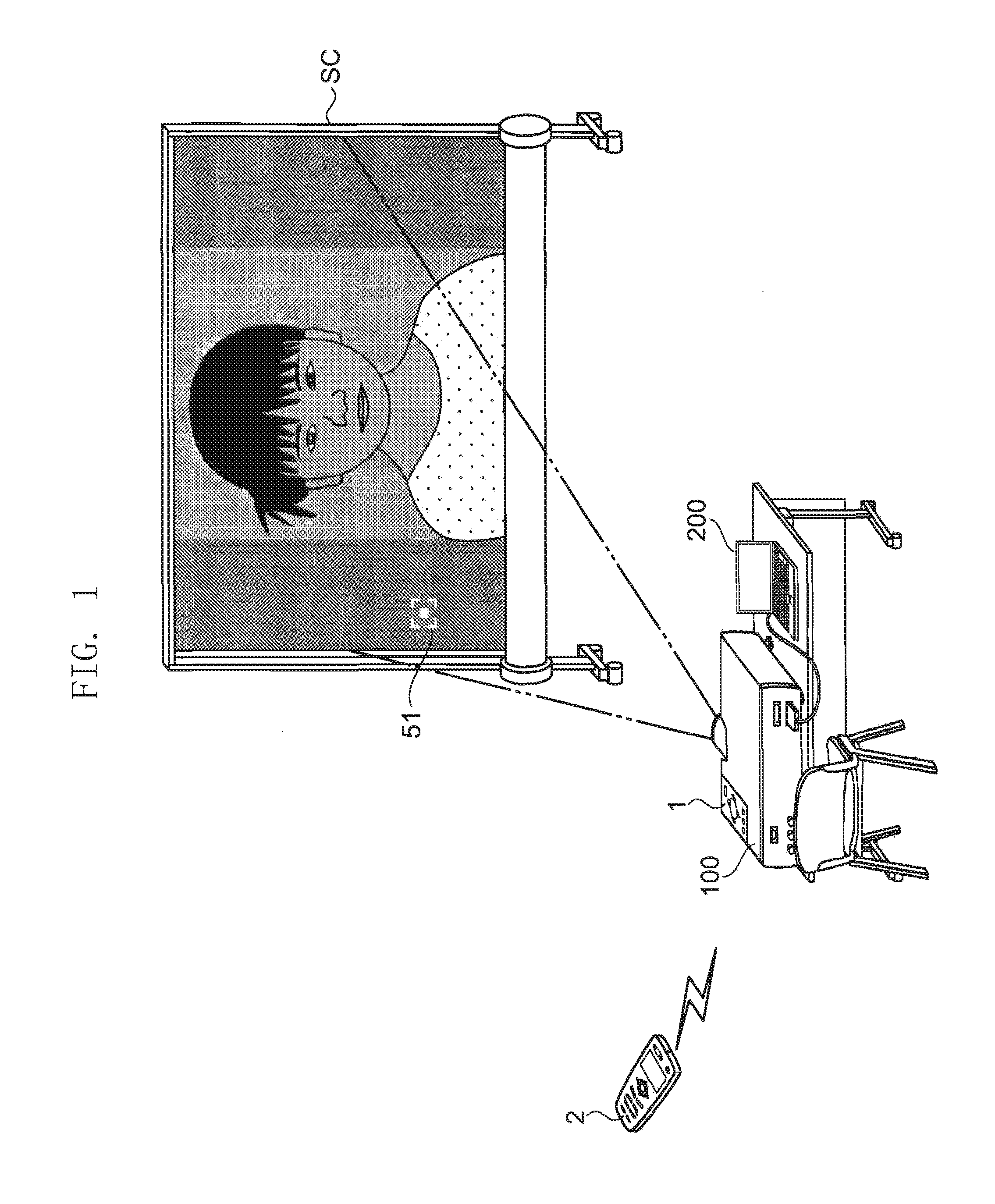
[0164]FIG. 1 is a view showing a usage of a projector according to a first embodiment of the invention. The projector 100 as an image display apparatus projects an image on a screen SC based on image signals supplied from an image signal supply unit 200 such as a personal computer.
[0165] In order to increase image representing performance according to image contents or projection configuration, the projector 100 has two image adjusting functions and can adjust a grayscale value included in the image signal supplied from the image signal supply unit 200. The one of the image adjusting functions of the projector 100 is a “gamma” adjusting function for selecting a reference Y characteristic, that is, a basic grayscale characteristic among a plurality of selection items stored in advance. The other is a “color mode” adjusting function for selecting a desired color mode among a plurality of selection items such as “natural”, “dynamic”, and “theater” in order to a...
second embodiment
[0360] Procedures of Second Image Adjusting Process 1: Up to Branch Screen
[0361]FIG. 14 is a flowchart for explaining operations of the projector 100 at a time of performing the “gamma” adjusting. FIG. 15A is a view showing an example of the selection screen, and FIG. 15B is a view showing an example of the branch screen.
[0362] Now, the operations of the process up to the branch screen according to the second embodiment in the image adjusting performed by the projector 10u according to the first embodiment are described with reference to mainly FIG. 14 and additionally FIGS. 15A, 15B, and 2. The same elements as those of the first embodiment are denoted by the same reference numerals, and redundant description is omitted.
[0363] The procedures and the manipulation screens in the process of the image adjusting according to the second embodiment are different from those of the process of the image adjusting according to the first embodiment. Therefore, the “grayscale adjusting progr...
modified example 1
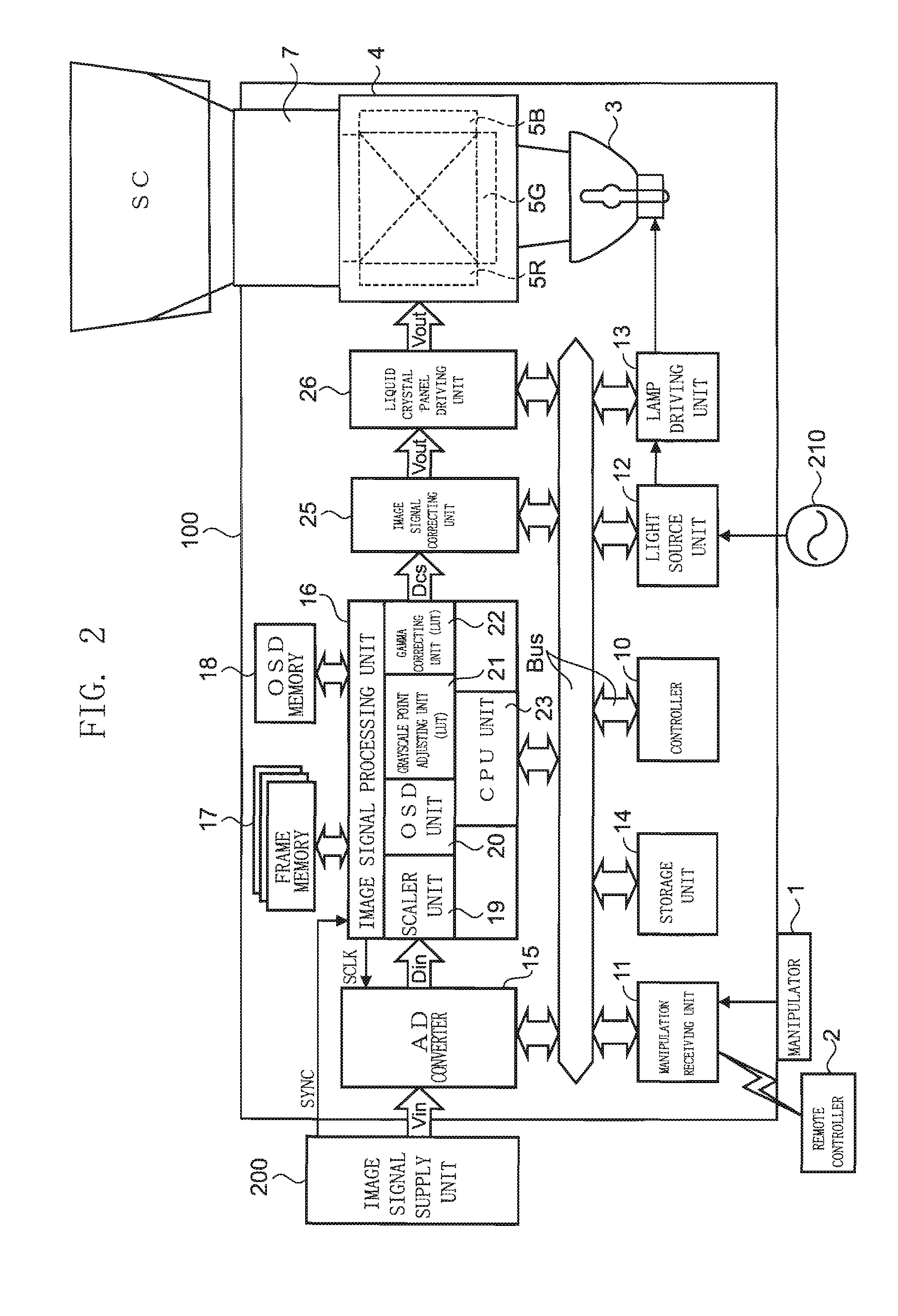
[0418] Modified Example 1 is described with reference to FIG. 2. In the aforementioned embodiments, the selection of the image portion or the adjusting of the output grayscale value in the cursor selection mode is performed by using the “up” and “down” buttons or the “left” and “right” buttons of the manipulator 1 or the remote controller 2. However, the invention is not limited thereto. For example, a track ball as a pointing device is provided to the remote controller 2, and a device driver corresponding to the track ball is stored in the storage unit 14. By manipulating the track ball, the selection of the image portion or the adjusting operation for the output grayscale value may be performed.
[0419] In such a construction of the projector 100, the adjusting manipulation can be efficiently performed.
PUM
 Abstract
Description
Claims
Application Information