
Direct light type backlight unit and liquid crystal display

a backlight unit and liquid crystal display technology, applied in the direction of illuminated signs, display means, instruments, etc., can solve the problems of reduced light efficiency, increased manufacturing costs of liquid crystal displays, low color realization rate of ccfl, etc., and achieve the effect of maximizing the diffraction efficiency of the grating

Active Publication Date: 2007-03-01
SAMSUNG ELECTRONICS CO LTD
View PDF1 Cites 73 Cited by
  • Summary
  • Abstract
  • Description
  • Claims
  • Application Information

AI Technical Summary

Benefits of technology

[0012] The present invention provides a backlight unit having a light source which allows light to be incident on a grating at an angle of incidence at which the diffraction efficiency of the grating can be maximized, and a large-sized liquid crystal display that does not include a color filter.

Problems solved by technology

When a color filter is used to realize a color image, light efficiency is decreased and manufacturing costs of a liquid crystal display are increased.
A cold cathode fluorescent lamp (CCFL) is used as a light source, but a CCFL has a low color realization rate and thus does not provide high image quality and is not appropriate for high resolution TVs or monitors.
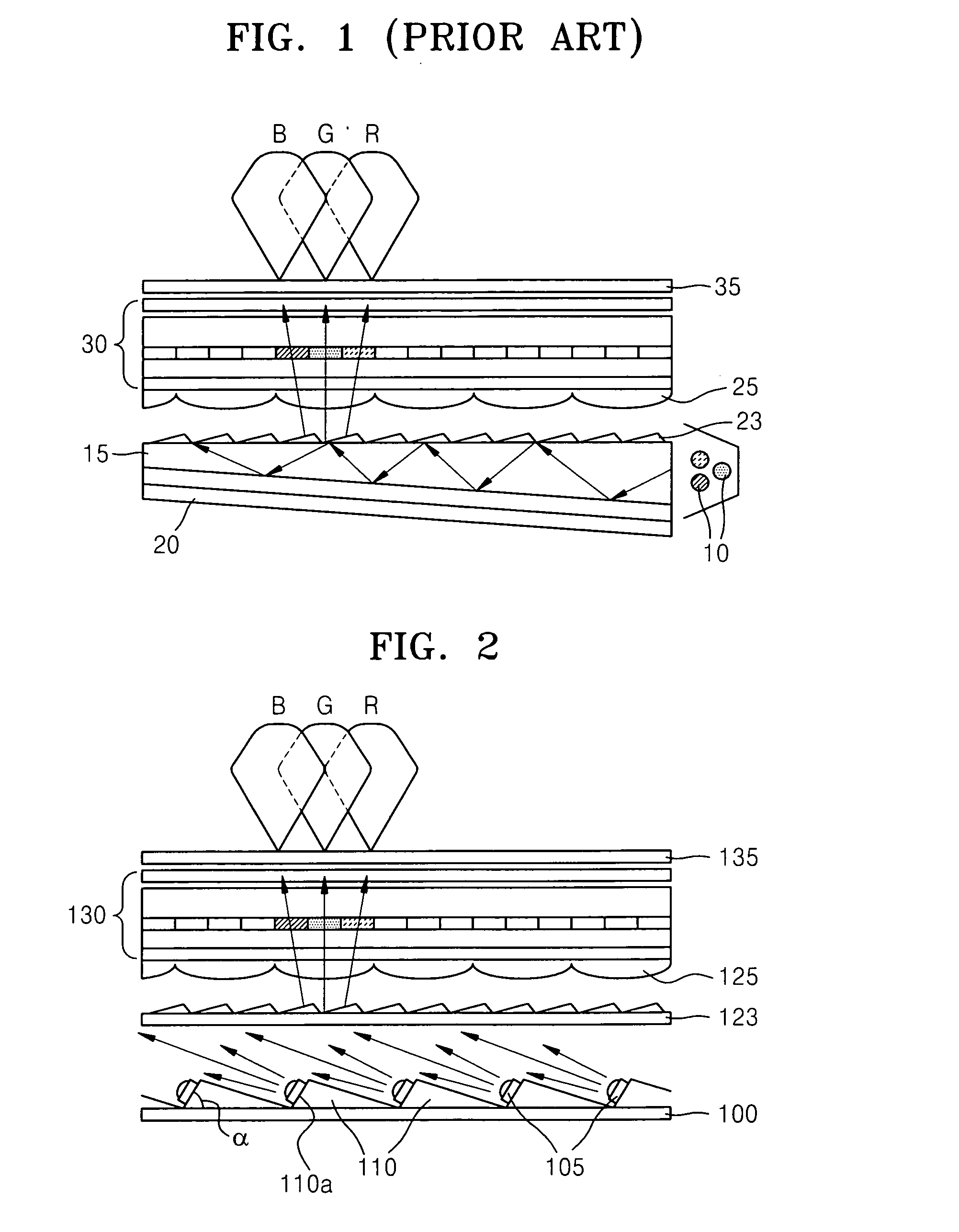
However, it is difficult to minutely control the angle of incidence of the light which is guided by the light guide panel 15 and incident on the grating 23.
As described above, in the edge light type backlight unit, it is difficult to control light to be incident on a grating at an optimal angle of incidence.
Since light is deflected from one direction to another by a light guide panel, light uniformity may not be secured.
Thus, the size of liquid crystal displays is limited.

Method used


Image

  • Direct light type backlight unit and liquid crystal display
  • Direct light type backlight unit and liquid crystal display

Examples


Embodiment Construction

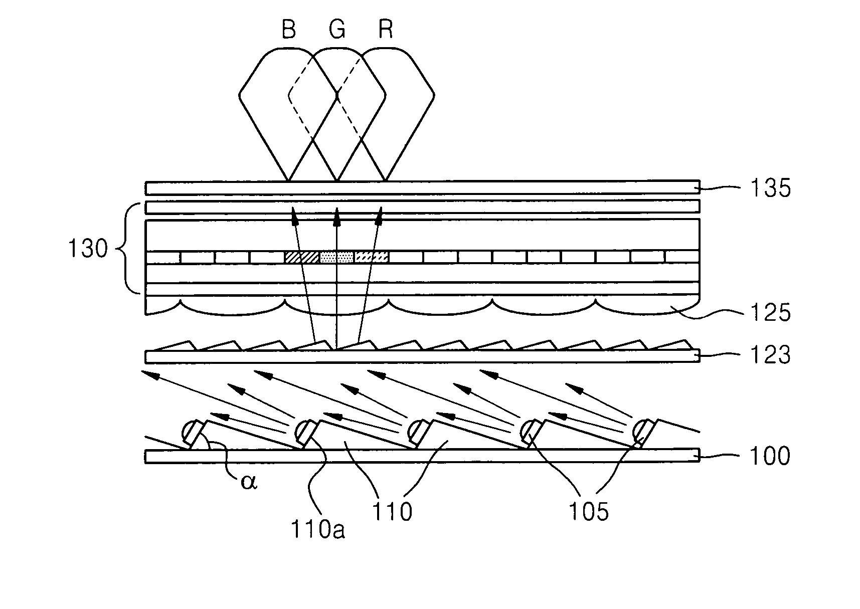
[0020] Referring to FIG. 2, a backlight unit according to an illustrative, non-limiting embodiment of the present invention includes direct light type light emitting devices 105 which are disposed below a liquid crystal panel 130 and a grating 123 diffracting incident light from the light emitting devices 105 at different angles according to wavelength.

[0021] The light emitting devices 105 are disposed at a predetermined angle α on a substrate 100, and thus, most of the light emitted from the light emitting devices 105 is incident at a predetermined angle to the grating 123. To install the light emitting devices 105 inclined to the substrate 100, installation units 110 having mounting surfaces 110a are formed on the substrate 100 and the light emitting devices 105 are installed on the mounting surfaces 110a. Thus, a backlight unit having light emitting devices which emit controlled light incident on the grating 123 at an optimal angle of incidence can be realized.

[0022] The light ...


PUM


Abstract

A direct light type backlight unit and a liquid crystal panel employing the same. The backlight unit includes a plurality of light emitting devices disposed at a predetermined angle on a substrate; and a grating which diffracts incident light from the light emitting devices at different diffraction angles to separate the incident light into a plurality of colored light beams. The backlight unit and the liquid crystal display include direct light type light sources emitting light at an optimal angle to provide maximum diffraction efficiency of the grating, which allows color image realization without the use of a color filter.

Description

CROSS-REFERENCE TO RELATED PATENT APPLICATION [0001] This application claims priority from Korean Patent Application No. 10-2005-0078883, filed on Aug. 26, 2005, in the Korean Intellectual Property Office, the disclosure of which is incorporated herein in its entirety by reference. BACKGROUND OF THE INVENTION [0002] 1. Field of the Invention [0003] The present invention relates to a direct light type backlight unit and a large-sized liquid crystal display that does not include a color filter. [0004] 2. Description of the Related Art [0005] In general, liquid crystal displays (LCDs), which are flat panel displays used in lap top computers, desktop computers, LCD TVs, and mobile communication terminals, are light receiving devices which do not form images by themselves, but by receiving light from an external source, and need a backlight unit in addition to a liquid crystal panel. A backlight unit is installed behind a liquid crystal display and serves as a light source to emit light....

Claims


Application Information

Patent Timeline
IPC IPC(8): G09F13/04
CPCG02F1/133621G02F1/133603G02F1/1335
Inventor PARK, SANG-MOO
Owner SAMSUNG ELECTRONICS CO LTD
Learn More