Plane diffraction grating based on surface normal rotation and its application to an optical system

a technology of normal rotation and diffraction grating, which is applied in the direction of optical radiation measurement, instruments, spectrometry/spectrophotometry/monochromators, etc., can solve the problem of only maximizing diffraction efficiency at a certain wavelength, and achieve the effect of maximizing diffraction efficiency

Inactive Publication Date: 2005-01-18
JAPAN ATOM ENERGY RES INST +1
View PDF6 Cites 1 Cited by
  • Summary
  • Abstract
  • Description
  • Claims
  • Application Information

AI Technical Summary

Benefits of technology

The diffraction grating is rotated at a rotational center. The off-axis area from the center of rotation is illuminated by the incident converging beam and optimized to maximize diffraction efficiency for the respective wavelength.

Problems solved by technology

When such a diffraction grating is employed in a constant deviation angle monochromator in which wavelength scanning is done by rotating a diffraction grating about an axis parallel to the grooves of the diffraction grating, however, the diffraction efficiency is maximized only at a certain wavelength but is not maximized at the other wavelengths.

Method used


Image

  • Plane diffraction grating based on surface normal rotation and its application to an optical system
  • Plane diffraction grating based on surface normal rotation and its application to an optical system
  • Plane diffraction grating based on surface normal rotation and its application to an optical system

Examples


first example

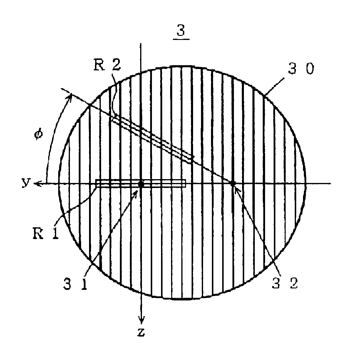
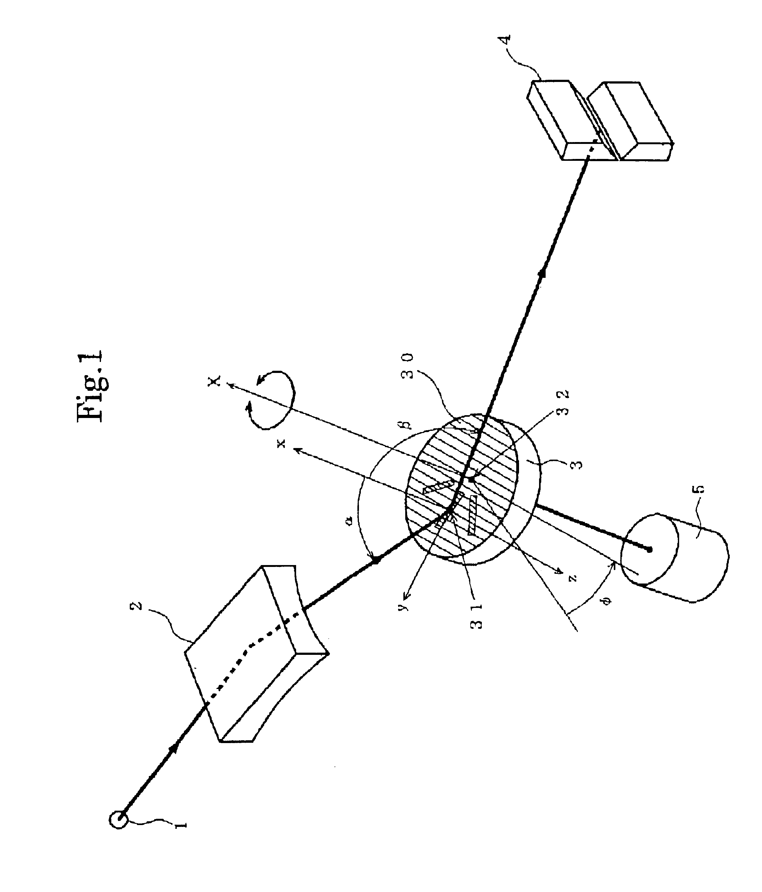
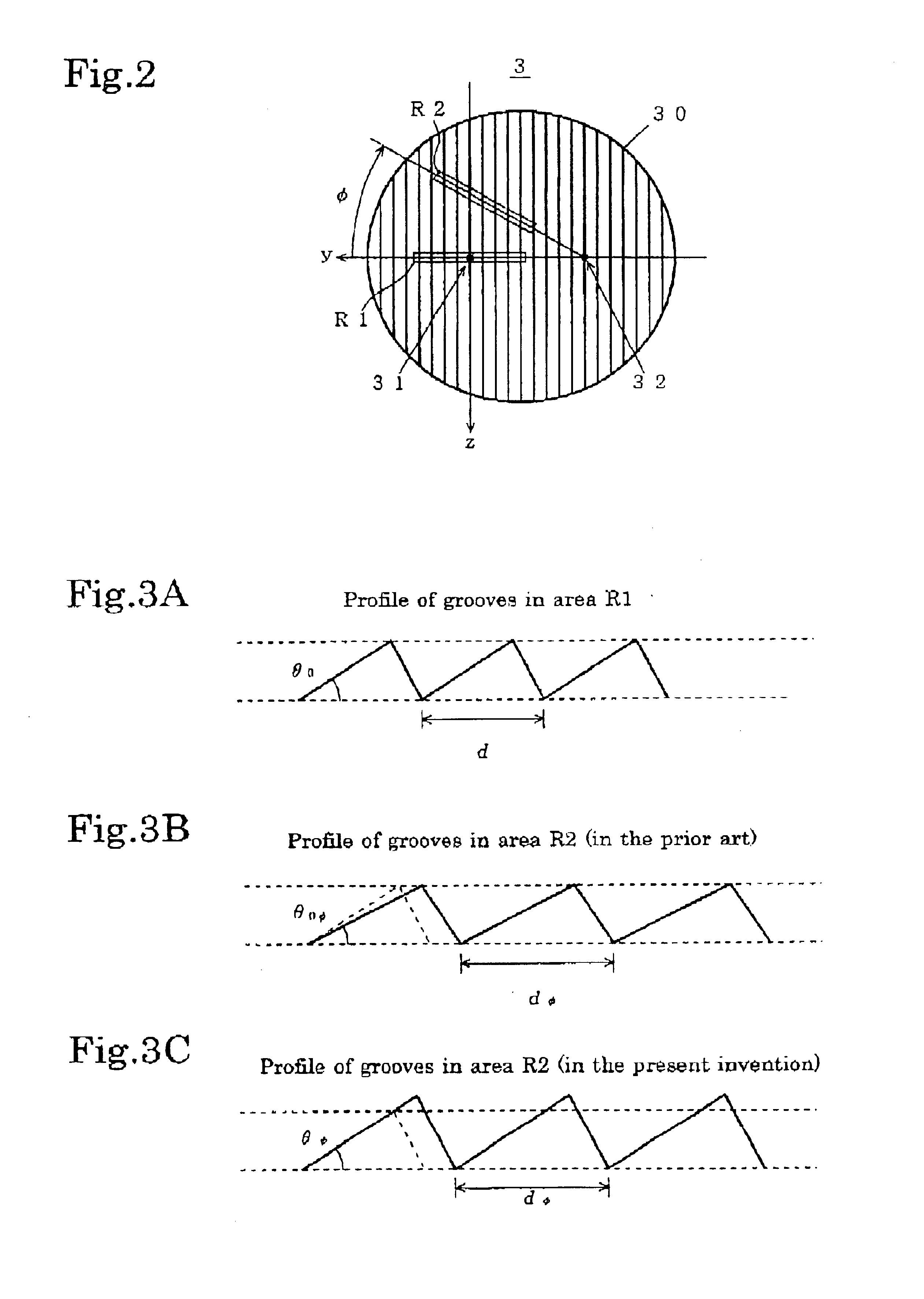
An example using a blazed type diffraction grating is first described referring to FIGS. 2 and 3A-3C. FIG. 3A show the profile of the grooves of the diffraction grating in the area R1, in which the blaze angle is denoted as θ0, and the grating constant is denoted as d. Supposing the light diffracted by the area R1 has the wavelength λ0, it is known that the diffraction efficiency in maximized for the light of wavelength λ0 by setting the blaze angle θ0 as follows: θ0=α+β2.(1)

In conventional blazed tape diffraction gratings, the blaze angle is the same throughout the entire surface 30. When such a diffraction grating is used in the above described monochromator, the diffraction efficiency is not maximized for the light of wavelengths other than λ0 (or at the position φ≠0). This is explained as follows: When the diffraction grating 3 is at the position φ (≠0) and the incident light beam illuminates the area R2, the profile of the grooves along the length of the area R2 is as shown by ...

second example

Another example using a blazed type diffraction grating is then described. The surface of the grooves of the diffraction grating 3 is covered with a multiple-layer coating to improve reflectivity and thus the diffraction efficiency. Suppose the unit thickness of the multiple-layer coating in the linear area R1 at the rotational position φ=0 is db0. In order to improve the diffraction efficiency for the light of wavelength λ0, the unit thickness db0 should satisfy the following Bragg equation:

mbλ0=2db0Rα0 cos(α−θ0),  (6)

where Rα0 is given by

Rα0=√{square root over (1−(2δ−δ2) / cos2α)},  (7)

in which δ=1−n, where n is the average refractive index of the multiple-layer coating for wavelength λ0.

In the linear area R2 of the rotational position φ(≠0), the unit thickness dbφ of the multiple-layer coating for the improved diffraction efficiency for the wavelength λ is calculated as follows: When the rotational position of the diffraction grating 3 is φ, the angle between the incident ray and t...

third example

The present invention is embodied in a monochromator using a laminar type diffraction grating. It is generally known (for example, K. H. Hellwege, Z. Phys. Vol. 106(1937), pp. 588-596) that the diffraction efficiency for the primary order diffraction light of wavelength λ0 is maximized and the diffraction light of even-number orders are decreased by setting the depth h0 of the grooves of the laminar type diffraction grating as: h0=λ02⁢(cos⁢ ⁢α+cos⁢ ⁢β).(11)

The wavelength λ corresponding to the rotational position φ of the diffraction grating 3 is given by λ=λ0cos⁢ ⁢ϕ.(12)

The optimal depth hφ of the grooves in the linear area R2 of the rotational position φ for maximizing the diffraction efficiency is hϕ=λ02⁢(cos⁢ ⁢α+cos⁢ ⁢β)⁢cos⁢ ⁢ϕ.(13)

By setting the depth of the grooves in the area R2 at the optimal depth hφ given above, the diffraction efficiency is always maximized irrespective of the rotational position of the diffraction grating 3 and for any scanning wavelength λ.


PUM


Abstract

A plane diffraction grating based on surface normal rotation according to the present invention is designed so that the profile of the grooves at a radial area is determined depending on a rotational position of the area about a rotational center defined as a foot of the rotational axis on the surface of the plane diffraction grating. An optical system such as a spectrometer or a monochromator according to the present invention uses such a plane diffraction grating, and requires a special arrangement. The optical system includes: a plane diffraction grating as described above; a mechanism for rotating the plane diffraction grating about the rotational axis; an incidence optical system for casting a converging beam of light on a point of the surface of the plane diffraction grating, where the point is set apart from the rotational center. As the diffraction grating is rotated about the rotational center, the point on which the incident converging beam of light is cast rotates about the rotation center, where the diffracting condition is optimized anywhere around the rotational center or for any scanning wavelength. The surface of the plane diffraction grating can be covered with a multiple-layer coating to improve diffraction efficiency. When such a multiple-layer is coated, the unit thickness of the multiple-layer coating at an area is also determined depending on the rotational position of the area about the rotational center.

Description

The present invention relates to a spectrometer or a monochromator based on surface normal rotation, and to a plane diffraction grating optimized for use in such a spectrometer or a monochromator.BACKGROUND OF THE INVENTIONIn designing a diffraction grating employed in a spectrometer or a monochromator, the profile of the grooves should be designed so as to reveal the highest diffraction efficiency as much as possible. In a blazed type diffraction grating having a saw-like profile, for example, the blaze angle should be optimized, and in the laminar type diffraction grating having grooves of a rectangular profile, the depth of the grooves and the duty ratio should be optimized, to obtain the highest diffraction efficiency.When such a diffraction grating is employed in a constant deviation angle monochromator in which wavelength scanning is done by rotating a diffraction grating about an axis parallel to the grooves of the diffraction grating, however, the diffraction efficiency is m...

Claims


Application Information

Patent Timeline
Patent Type & Authority Patents(United States)
IPC IPC(8): G01J3/00G01J3/18G01J3/06G01J3/12G02B5/18
CPCG01J3/06G02B5/1828G01J3/189G01J3/1804
Inventor KOIKE, MASATOSANO, KAZUOHARADA, YOSHIHISA
Owner JAPAN ATOM ENERGY RES INST
Why Eureka
Try Eureka