Backlight unit for test device of LCD panel

a backlight unit and liquid crystal display technology, which is applied in semiconductor devices, lighting and heating apparatus, instruments, etc., can solve the problems of increasing the cost of operating the tester, affecting the test results, so as to prevent brightness deviation and increase the lifetime of the backlight unit

Active Publication Date: 2007-03-01
LG DISPLAY CO LTD
View PDF8 Cites 61 Cited by
  • Summary
  • Abstract
  • Description
  • Claims
  • Application Information

AI Technical Summary

Benefits of technology

[0020] An advantage of the present invention is to provide a backlight unit for a test device of an LCD panel, in which heat generated by emission of the backlight is removed to increase the lifetime of the backlight unit.
[0021] Another advantage of the present invention is to provide a backlight unit for a test device of an LCD panel, in which a light source is uniformly supplied to the LCD panel to prevent brightness deviations from occurring.
[0022] Additional features and advantages of the invention will be set forth in the description which follows, and in part will be apparent from the description, or may be learned by practice of the invention. The objectives and other advantages of the invention will be realized and attained by the structure particularly pointed out in the written description and claims hereof as well as the appended drawings.
[0023] To achieve these and other advantages and in accordance with the purpose of the present invention, as embodied and broadly described, a backlight unit for a test device of an LCD panel incl

Problems solved by technology

However, the related art test device of the LCD panel has the following problems.
However, these types of backlight 4b have a problem in that frequent blinking on and off these lamp types rapidly decreases the lifetime of the lamp.
The shortened lifetime results in the backlight 4b having to be frequently replaced increa

Method used


Image

  • Backlight unit for test device of LCD panel
  • Backlight unit for test device of LCD panel
  • Backlight unit for test device of LCD panel

Examples


first embodiment

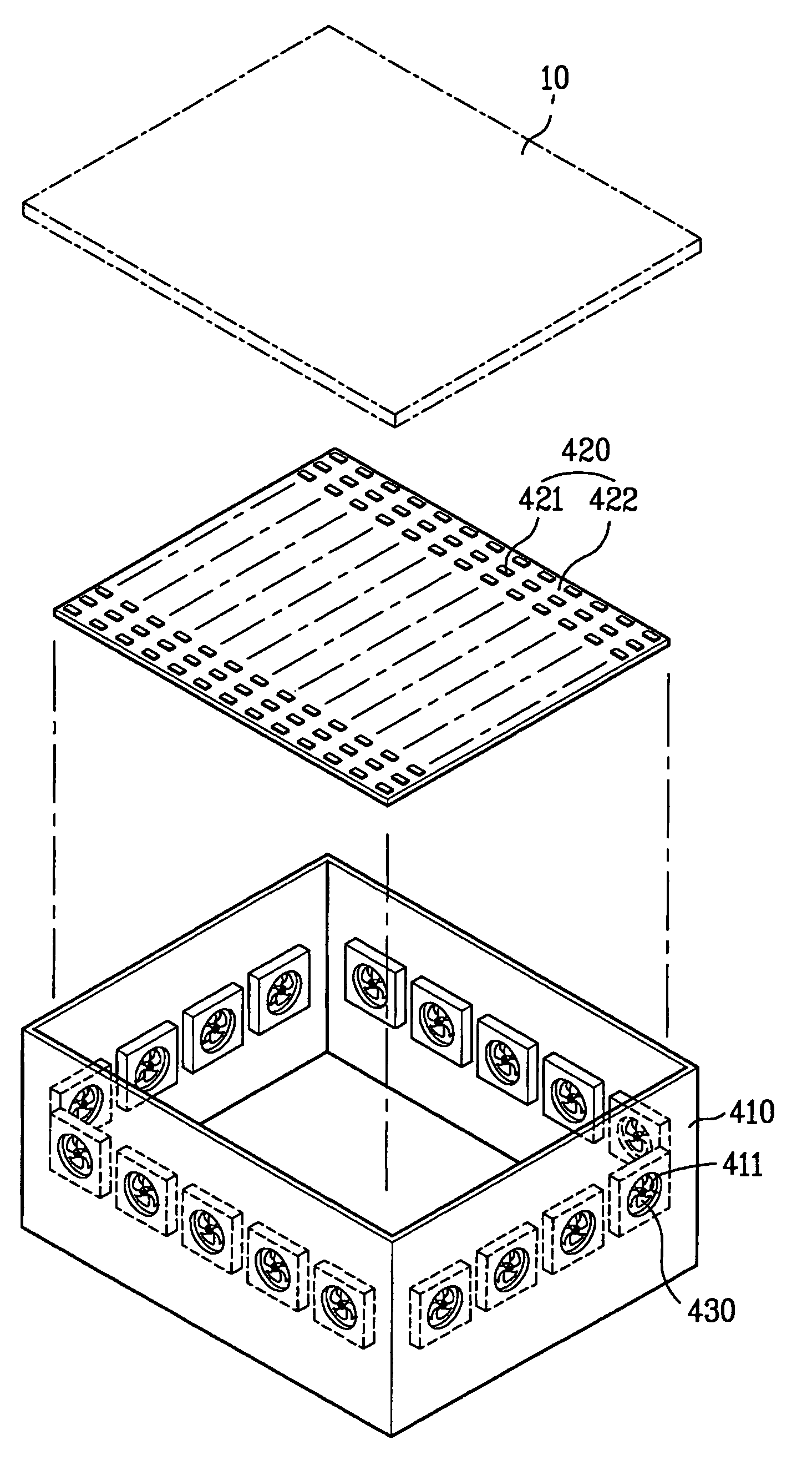
[0042]FIGS. 3 and 4 are an exploded perspective view and a side sectional view illustrating a backlight unit for a test device of an LCD panel according to the present invention.

[0043] As shown in FIGS. 3 and 4, the backlight unit for a test device of an LCD panel according to the first embodiment of the present invention includes a chamber 410, a backlight 420, and a plurality of circulating fans 430.

[0044] The chamber 410 has a rectangular box shape having a predetermined volume therein, with an open top surface. The chamber 410 is provided with a plurality of through holes 411 along the perimeter of the chamber 410. An inner space of the chamber 410 communicates with its outer space through the through holes 411.

[0045] The through holes 411 may be formed along the entire of the perimeter of the chamber 410, along two opposing portions of the perimeter, or along one portion of the perimeter.

[0046] Alternatively, the chamber 410 may have a cylindrical shape or a polygonal box sh...

second embodiment

[0064]FIGS. 5 and 6 illustrate a backlight unit according to the present invention.

[0065] As shown in FIGS. 5 and 6, the backlight unit according to the second embodiment of the present invention includes a chamber 410, a backlight 420, circulating fans 430, and a heat-radiating member 440.

[0066] The second embodiment of the present invention differs from the first embodiment in that a heat-radiating member 440 is further provided in the backlight unit.

[0067] The cooling effect of air circulating on the PCB substrate 422 is increased when air from outside the chamber 410, which is vented into the chamber 410, makes effective contact with the PCB substrate 422. In the second embodiment of the present invention, the heat-radiating member 440 is used to increase the effective contact area between the circulated air and the PCB substrate 422.

[0068] Hereinafter, the construction of the second embodiment is described in detail.

[0069] The chamber 410, the backlight unit 420 and the cir...

third embodiment

[0082]FIGS. 7 and 8 illustrate a backlight unit according to the present invention.

[0083] As shown in FIGS. 7 and 8, the backlight unit according to the third embodiment of the present invention includes a chamber 410, a backlight 420, and a refrigerant pipe 450.

[0084] In the third embodiment of the present invention, the refrigerant pipe 450 is provided inside the chamber 410 to facilitate cooling of the inside of the chamber 410 of the backlight unit. The refrigerant pipe 450 is designed such that a low temperature refrigerant flows therein.

[0085] In other words, the third embodiment of the present invention provides a reduced temperature inside the chamber 410 due to the flow of refrigerant of a low temperature within the refrigerant pipe 450.

[0086] Hereinafter, the third embodiment of the invention will be described in more detail.

[0087] The chamber 410 and the backlight unit 420 of the backlight unit according to the third embodiment of the present invention are the same as...


PUM


Abstract

A backlight unit for a test device of an LCD panel is disclosed. The backlight unit includes: a chamber enclosing a predetermined space, the chamber being provided with a plurality of through holes formed around the chamber perimeter to allow air flow between the interior and exterior of the chamber; a backlight provided in the chamber to emit a light to an LCD panel positioned in the chamber; and a plurality of circulating fans provided in the chamber to circulate air inside the chamber.

Description

[0001] This application claims the benefit of Korean Patent Application No. 10-2005-0081403, filed on Sep. 1, 2005, which is hereby incorporated by reference for all purposes as if fully set forth herein. BACKGROUND OF THE INVENTION [0002] 1. Field of the Invention [0003] The present invention relates to a test device for a liquid crystal display (LCD) panel, and more particularly, to a backlight unit having increased lifetime for an LCD panel test device. [0004] 2. Discussion of the Related Art [0005] One type of test device of the related art for a liquid crystal display (LCD) panel allows a naked eye evaluation of whether the LCD panel is bad or good. [0006]FIGS. 1 and 2 illustrate a related art test device for an LCD panel. [0007] As shown in FIGS. 1 and 2, the related art test device for an LCD panel includes a tester 2 and a loading / unloading unit 7. The tester 2 is arranged at one side of a main body 1 to test an LCD panel 10. The loading / unloading unit 7 is arranged at one s...

Claims


Application Information

Patent Timeline
IPC IPC(8): F21V29/00
CPCF21V29/30F21Y2101/02H05K7/20972G02F1/133603G02F2001/133628G02F1/1309F21Y2115/10G02F1/133628G02F1/1335F21V29/59
Inventor KANG, DONG WOOEOM, SOUNG YEOULKIM, BONG CHULYANG, KI SOUB
Owner LG DISPLAY CO LTD
Why Eureka
Try Eureka